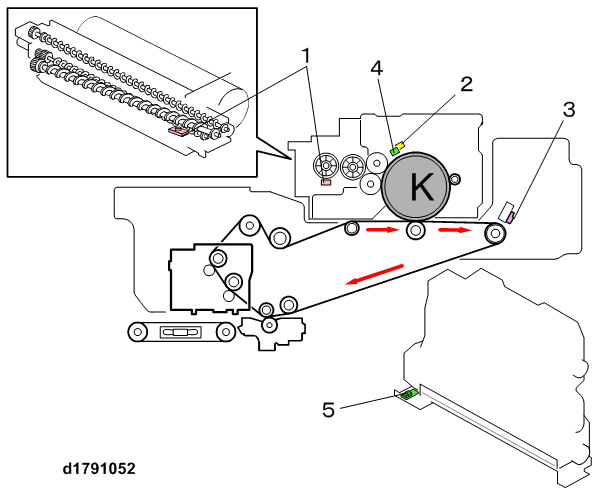
The image creation engine of the machine employs an image-to-drum transfer system comprised of several elements working together.
No. | Name |
|---|---|
1 | TD Sensor |
2 | Drum Potential Sensor |
3 | ID Sensor |
4 | Temperature/Humidity Sensor (PCDU) |
5 | ITB Temperature/Humidity Sensor |
The process control sensors are located around the drum. These sensors work together during potential control and toner supply control.
- TD Sensor. Mounted under the toner supply unit, measures the amount toner in the developer/toner mixture. This sensor has an embedded ID chip that records and stores information about the image density level.
- Drum Potential Sensor. A non-contact sensor above the drum that measures the surface electrical potential of the drum immediately after the drum has been charged by the charge unit.
- ID Sensor. A non-contact sensor above the ITB that reads a pattern projected onto the drum to determine the amount of toner on the drum (level of image density).
- Temperature/Humidity Sensors. Two temperature/humidity sensors, one above the PCDU and one below the used toner bottle, monitor the temperature around the PCDU and the ambient temperature.
- ITB Temperature/Humidity Sensor. Constantly measures temperature and humidity around the ITB. The machine uses these readings to adjust the amount of charge applied to the areas of the belt that contact the leading edge, center, and trailing edge of the paper.