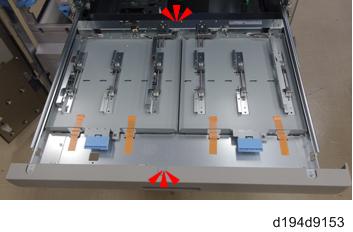
- Remove all visible external tapes on the external surfaces.
- Remove the six covers on the right side of the downstream vacuum feed LCIT.
- Lift the rear right cover [A] of the downstream vacuum feed LCIT and remove it (
x6).
- Lift the rear left cover [A] of the downstream vacuum feed LCIT and remove it (
- Locate the installation positions of the four units
[A]: Detent unit
[B]: Entrance motor unit
[C]: Exit motor unit
[D]: Control board - Attach the detent unit [A] (
- Attach the entrance motor unit [A] (
- Check that the belt is not out of position. If the belt is out of position, this can cause a horizontal transport unit jam.
- Before fastening the motor unit [A], slide it to the left.
- Insert the tip of a thin screwdriver or other tool into the gap to check the belt [B] tension.
- Attach the exit motor unit [A] (
- Attach the control board [A] and fan assembly [B] (
- Tighten the fan assembly [B] and control board [A] together (blue circles).
Connect the drawer connector harness [A] and the motor harness [B] to the control board (
x4).
CN208
CN210
CN207
CN205
- Route the drawer connector harness and the motor harness as shown below, and then insert the connectors into the relay connectors in the frame.
- Attach the edge saddles [A] and [B] provided with this option to the following locations.
- Route the drawer connector harness and motor harness as shown below. Then connect the connectors to the drawer connector and motor (
x4).
Control Board
Upper Side
Exit Motor Unit - Route the harness [A] so that the bind shown in the red circle is located above the edge saddle [B].
- Connect the cooling fan harness [A] and the communication harness [B] to the main board of the vacuum feed LCIT (
Route the cooling fan harness and the communication harness as shown below. Then connect the connector of the cooling fan harness to the cooling fan, and insert the connector of the communication harness into the relay connector in the frame (
CN37
CN13
Main Board of the Vacuum Feed LCIT
Control Board- Route the cooling fan harness so that the connector [A] is located above the clamp [B].
- Connect the interlock switch harness [A] to the control board (
Insert the connector of the interlock switch harness into the relay connector in the frame through the clamp [B] provided with this option.
CN216
- Connect the interface harness [A] to the main board of the vacuum feed LCIT (
Route the harness as shown below through the clamps [B] provided with this option. (
CN29
CN30
Connect the interface harnesses to the control board (
CN245
CN217
CN201
CN203
CN202
-
-
- Route the interface harnesses so that the bands of the harness are located below the edge saddle.
- Pull away the harness [A].
- Attach the edge saddle [B] provided with this option.
- Insert the connector into the relay connector in the frame through the clamp.
- Pull paper tray 1 from the vacuum feed LCIT.
- Lift the tray 1 front cover and remove the screws [A] (
Remove the screws [B] (
x2).
- Remove the tray 1 front cover beforehand so that it does not hit the floor when putting paper tray 1 on the floor.
Remove paper tray 1 [A] from the vacuum feed LCIT (
- Two or more customer engineers are required to lift the paper feed unit off the rails because the paper feed unit is extremely heavy (approx.30kg). Work carefully when lifting or moving it.
- Remove the horizontal transport front cover [A] from the vacuum feed LCIT (
- Remove the stay [A] from the horizontal transport front cover (
- Remove the brackets [A] and [B] from the horizontal transport front cover (
Attach the horizontal transport front cover to the horizontal transport unit (
- Do not remove shipping tapes when turning over the horizontal transport unit to attach the screws to the back side.
- Attach the wheels [B] to the stay [A] removed earlier (
- Attach the right slide rail [A] provided with this option to the vacuum feed LCIT (
- Look for the "L" engraved on the left rail and the "R" engraved on the right rail.
- Attach the left slide rail [A] provided with this option to the vacuum feed LCIT (
- Attach the rear screws after removing the fan bracket [A].
- Remove the upper inner cover from the vacuum feed LCIT.
- Open the front door.
- Remove the two levers [A] (
- Remove the knob [B] (
- Raise the U9 jam removal plate and remove the handle [A] (
- Three knobs [A] (
- Upper inner cover [B] (
- Remove the bracket [A] and knob [B] from the jam removal lever provided with this option (
- Attach the bracket [A] removed earlier to the vacuum feed LCIT (
- Set the jam removal lever [A] through the hole in the slide rail as shown below.
- Check the position and make sure it is correct as shown below.
- Fix the jam removal lever to the bracket (
- Cut out the plastic knockouts for the jam removal lever from the upper inner cover.
- Paste the decal for the U10 knob [A] to the lower side of the point where you cut.
- Re-attach the upper inner cover.
- Attach the stay [A], to the vacuum feed LCIT (
Pick up the horizontal transport unit at its rear center and front center.
- Always hold the transport unit by its front and rear center.
- Set the horizontal transport unit on the slide rails.
- Hang the tabs located at the four corners of the slide rail into the cutouts in the horizontal transport unit.
- Use the screws [A] provided to fasten the tray (
- Push in the horizontal transport unit.
- Re-attach the covers.