Print Area
Check that the adjustment meets the product specification.
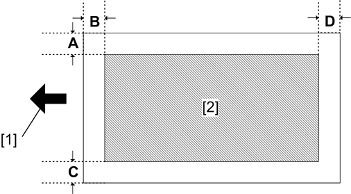
- [1]: Paper feed direction
- [2]: Print area
Adjustment Reference Values
- B: Leading edge (Sub scanning direction): 3.0 ± 1.5 mm
- D: Trailing edge (Sub scanning direction): 3.0 mm
- C: Left (Main scanning direction): 2.0 ± 1.5 mm
- A: Right (Main scanning direction): 2.0 mm
Adjustment Procedure
Enter the SP mode, and select the test pattern (15: Trim Area) with SP2-109-001 (Test Printing: Pattern Selection).
Print out a test pattern with SP2-109-002 (Test Printing: 1 Sheet Printing).

Print a test pattern, and then adjust the leading edge registration in the SP mode to the optimum value.
Do the leading edge registration adjustment.
1) Check the leading edge registration for each paper trays and adjust them with SP1-001.
SP No.SP NameRangeSP1-001-001 User LeadEdge Reg: By-pass: Plain ±4.0 mm SP1-001-002 User LeadEdge Reg: Tray1: Plain ±4.0 mm SP1-001-003 User LeadEdge Reg: Tray2: Plain ±4.0 mm SP1-001-004 User LeadEdge Reg: Tray3: Plain ±4.0 mm SP1-001-005 User LeadEdge Reg: Tray4: Plain ±4.0 mm SP1-001-006 User LeadEdge Reg: Duplex: Plain ±4.0 mm 2) Input the value. Then press [#].
3) Generate a trim pattern to check the leading edge adjustment.Do the side-to-side registration adjustment.
1) Check the side-to-side registration for each paper trays and adjust them with SP1-002.
SP No.SP NameRangeSP1-002-001 User S-to-S Reg: By-pass ±4.0 mm SP1-002-002 User S-to-S Reg: Tray 1 ±4.0 mm SP1-002-003 User S-to-S Reg: Tray 2 ±4.0 mm SP1-002-004 User S-to-S Reg: Tray 3 ±4.0 mm SP1-002-005 User S-to-S Reg: Tray 4 ±4.0 mm SP1-002-006 User S-to-S Reg: Duplex ±4.0 mm 2) Input the value. Then press [#].
3) Generate a trim pattern to check the side-to-side registration adjustment.