- Remove the PCDU. (PCDU)
- Remove the upper cover. (Upper Cover (Printer), Upper Cover (MF))
- MF model: Remove the SCB with bracket. (SCB with the Controller Box (MF Model))
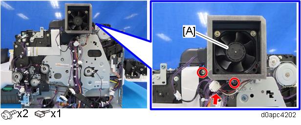
MF model: Remove the PCDU cooling fan (right) (FAN1) (right) with duct [A].
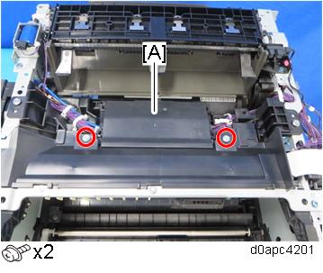
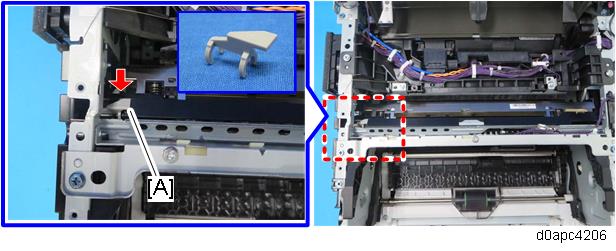
Remove the inner cover [A].
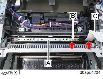
Push the LED unit [A] in.
Close the front door, or push the link on the left and right to push the LED unit in.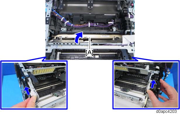
Disconnect the ground wire [B] and FFC [C] straight from the LED unit [A].

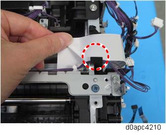
MF model: When re-connecting the FFC, attach it on the hook of the harness guide. The FFC must be connected straight.
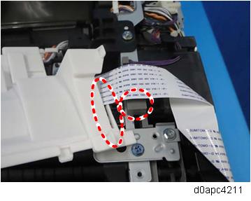
Printer model: When re-connecting the FFC, attach it on the hook of the harness guide and the hook of the inner cover. The FFC must be connected straight.
Return the LED unit to its original position.
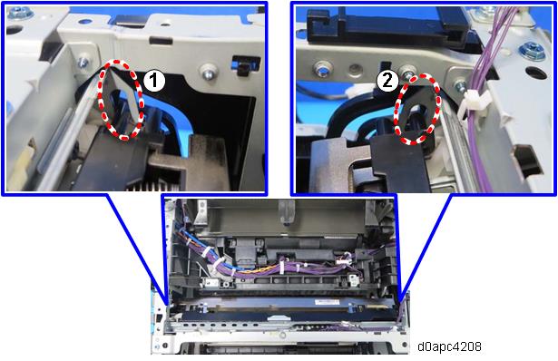
To unlock, open the front cover or use a small flathead screwdriver to raise the joints (circled in red) on the left and right.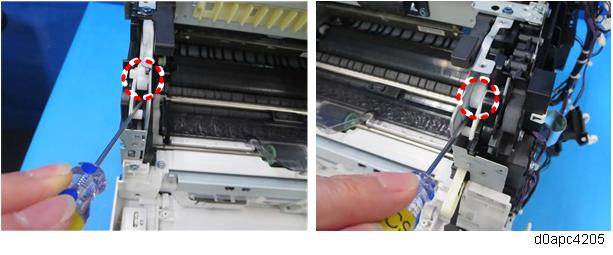
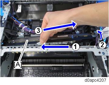
Remove the spacer [A].
Pull out the LED unit [A].
Slide the LED unit to left, and then pull out the LED unit's right shaft.
Work carefully when removing the LED unit to avoid hitting the lenses. A damaged lens could cause vertical streaks to appear on prints.
When reinstalling the LED unit work carefully to avoid touching the lens surfaces. When re-attaching the LED unit, make sure that the ends of the LED shaft at the top fit into the holes of the LED unitholder. Attach the left end of the LED unit first.
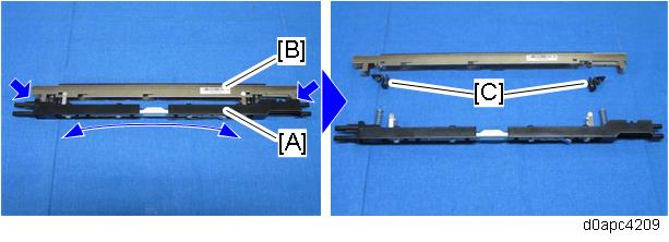
- Bend the stay [A] to release the left and right tabs, and then separate the stay from the LED head [B].
Remove the two spring holders [C] from the LED head.