Accessory
The FCU board of the service part contains the following items included in the package.
- FCU
- FFC
- Jumper
- Bracket
When you replace the FCU board, transfer the SRAM data from the old FCU board to the new FCU board.

The following data can be transferred:
- TTI
- RTI
- CSI
- Fax bit switch settings
- RAM address settings
- NCU parameter settings.
Replacement Procedure
- Remove the right cover. (Right Cover (MF))
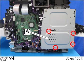
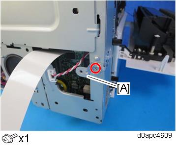
Remove the controller box lower cover [A].
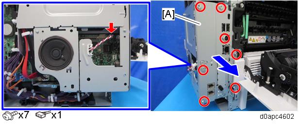
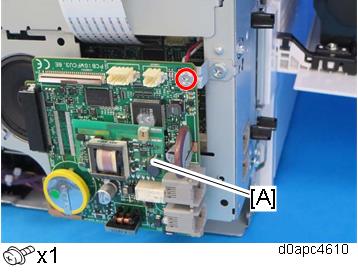
Disconnect the harness, and then pull out the interface cover [A] to remove it.
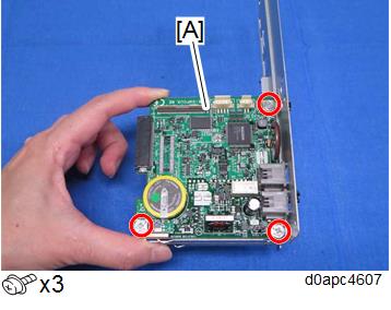
Remove the FCU [A].
Attach the jumper [A] on the removed FCU board [B]. The jumper comes with the new FCU board.
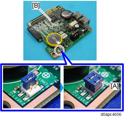
Change the position of the battery jumper [A] on the new FCU board [B].
If the battery jumper is not in the correct position, SC820 will occur.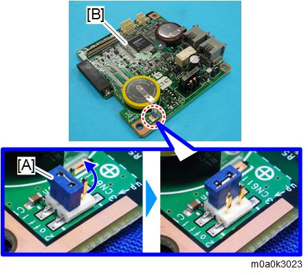
- Attach the new FCU board to the interface cover.
- Attach the interface cover to the machine, and then connect the harness.
Connect one end of the supplied FFC [A] into the CN603 connector [B] on the new FCU board.
Make sure that the blue tape of the flat cable faces outward.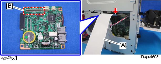
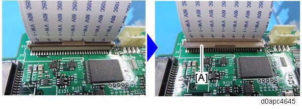
The FFC connector has a lock lever [A]. Tilt the lever to lock the FFC.
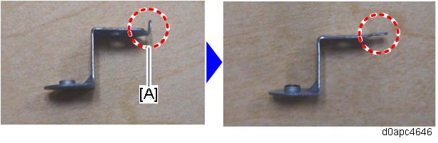
Use a pair of radio pliers to flatten the marked tab [A] against the bracket provided with the new FCU board.
Attach the bracket [A] above to the controller box.
Attach the old FCU board [A] to the bracket temporarily.
Mount the PCB and bracket so both are horizontal.
If the contact surface of bracket [A] cuts into the base plate as shown below, this could cause a short circuit between the element and the bracket and damage the PCB.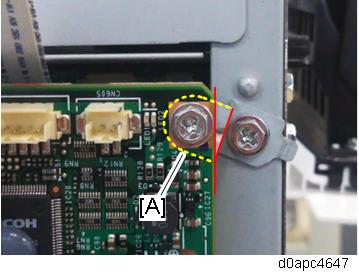
Connect the other end of the FFC [A] into the CN603 connector on the old FCU board.
Make sure that the blue tape of the flat cable faces outward.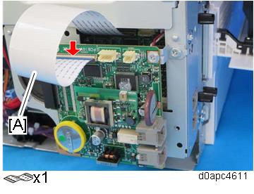
The FFC connector has the lock lever [A], so tilt the lever to lock the FFC.
Turn the main power ON.
The SRAM data transfer begins. Once the transfer is completed, it will beep to indicate that the process has been completed.
- The volume of the beeping is set to the same level as the speaker volume.
- If the speaker volume is set to off, the volume of the beeping is set to its initial factory-set level.
- If the machine does not beep, turn the main power OFF and then ON, and attempt data transfer again. Try several times if necessary.
- Be sure to check the transfer result after executing data transfer. If the transfer has failed, you need to specify settings manually in the SP mode.
- When "Ready" is displayed on the control panel, turn the power OFF, and remove the AC power plug from the receptacle.
- Disconnect the FFC from both FCU boards, and then remove the old FCU board with the bracket.
- Reattach the covers.
- Turn the main power ON.
- Enter the SP mode.
- Print the system parameter list from SP6-101 in the Fax SP menu, and then check the list to see whether the SRAM data has been transferred correctly.
Set the correct date and time from the [User Tools].
User Tools > Machine Features > System Settings > Timer Setting > Set Date/TimeIf any of the SRAM data was not transferred, input those settings manually.