- Remove the controller board. (Controller Board (Printer Model))
- Remove the upper cover. (Upper Cover (Printer))
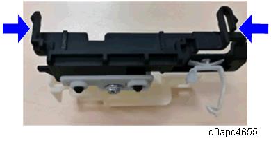
Release the two hooks to remove the harness guide [A].
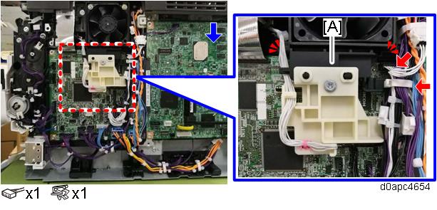

Remove the harness guide tab from the right side. Check the position of the harness guide tab in the photo below.
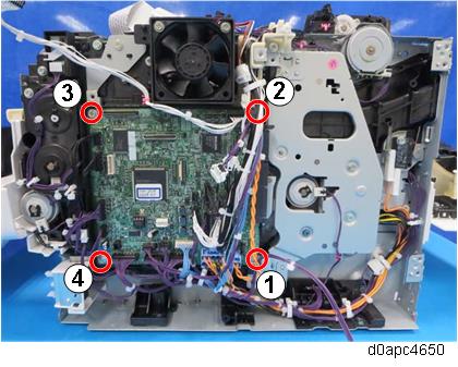
Remove the BCU [A].
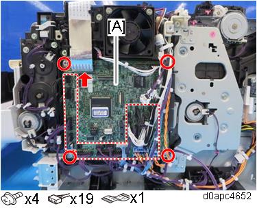
The board [A] is fastened to the bracket with three tabs. Before removing the BCU, confirm the locations of the tabs in the photo below.
When attaching the BCU, fasten the screws in the following order.
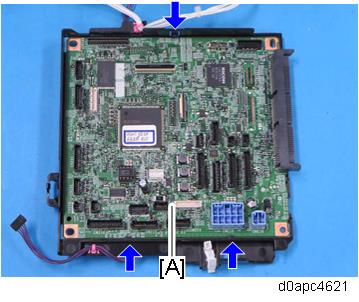
Remove the NVRAM [A] from the old BCU, and then install it on the new BCU [B].
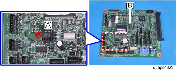
Install the NVRAM so that the indentation on the NVRAM faces the indentation mark on the controller board. If they are not installed correctly, the controller board may be damaged. Make sure that the NVRAM is correctly installed on the controller board by comparing the installation with the photo above.
Set the DIP switches [B] on the new BCU to the same settings as the old board.
- Attach the new BCU.
- Reattach the covers.
Turn the main power ON and enter the SP mode.
Enter the BCU serial number with SP5-811-004.
If the BCU serial number is not entered correctly, SC995-01 (serial number entry error) will occur.
- Power cycle the machine.