
Application settings and additional applications installed on the Smart Operation panel can be backed up automatically and can be restored. For details, refer to Automatic Backup/Restore for Application and Settings of SOP.
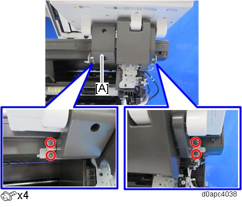
Remove the right cover. (Right Cover (MF))
Remove the scanner front cover. (Scanner Front Cover)
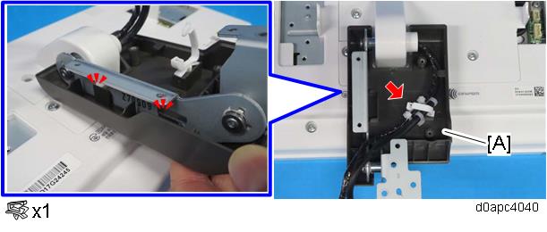
Disconnect the harnesses from the operation panel unit.
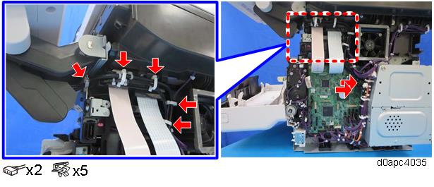

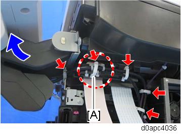
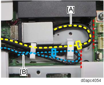
When reconnecting the harnesses, route the harnesses with the operation panel unit horizontal and clamp the harnesses. The clamp [A] fixes between the bands of the harnesses.
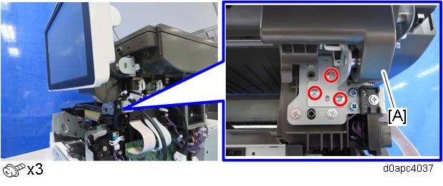
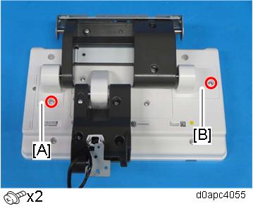
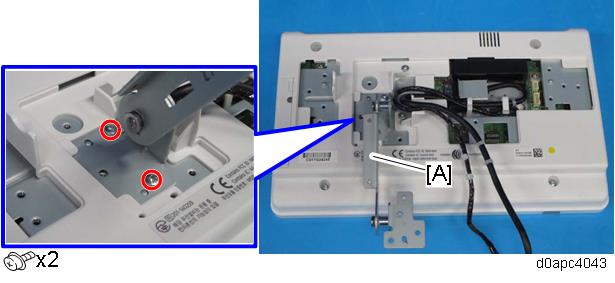
Set the operation panel vertically and remove the screws of the sub arm [A].
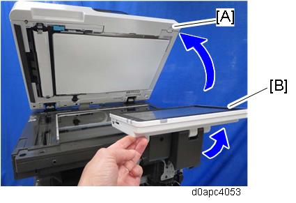
Open the SPDF [A], and then hold the operation panel [B] horizontal and lift it out.
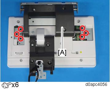
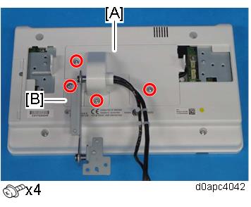
Remove the screws of the main arm [A], and then remove the operation panel unit.
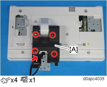
Turn over the operation panel unit, and remove the hinge covers [A] and [B].
Remove the main arm [A].
Remove the sub arm cover [A].
Release the two hooks to remove the sub-arm lower cover [A].
Remove the hinge covers [A] and [B].
Remove the sub-arm [A].
Release the clamps.
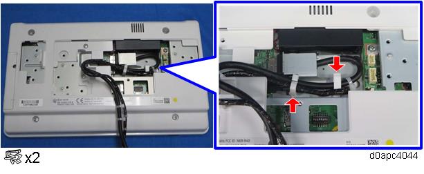
When clamping the USB cable [A], route the cable so it does not ride up on the operation panel PCB. Working carefully at the binding position, clamp the USB cable [A] and wire [B] at the positions shown below.
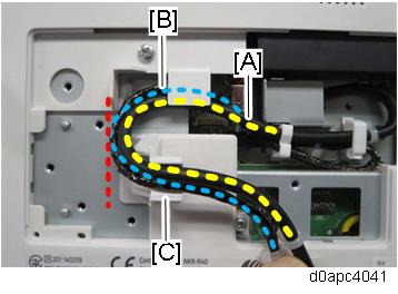
When you route the harnesses, place USB cable [A] so harness [B] is folded inside, bending it inward from inside the cover. Set the harness in the recess [C] so it will not be pinched by the hinge cover.
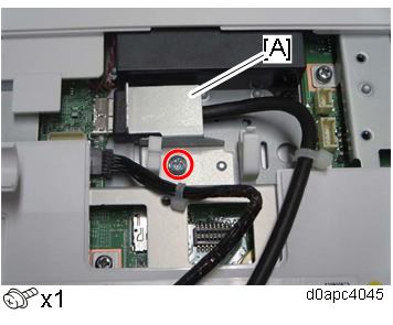
Remove the harness cover [A].
Disconnect the harnesses.
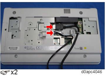
When re-connecting the harnesses, connect them straight as shown above.
When re-installing the operation panel unit, route the harnesses by referring to the photo in the reverse order.