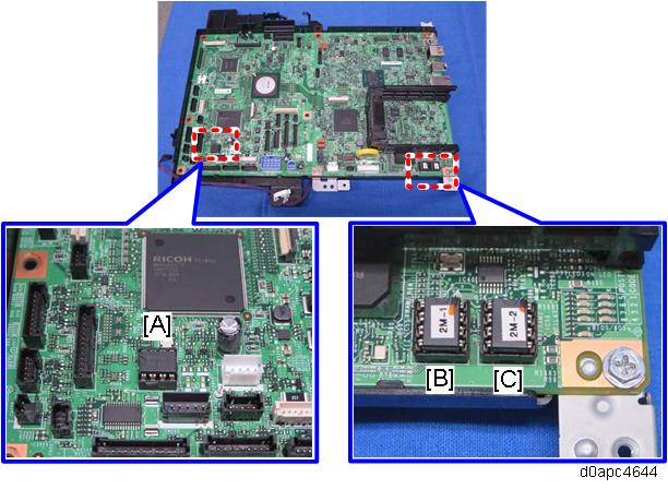
Three NVRAM are mounted on the SCB, one engine NVRAM [A] and two controller NVRAM [B] and [C]. When you replace an NVRAM, follow the steps in the engine NVRAM and controller NVRAM replacement procedures described below. Always replace controller NVRAM together as a paired set.
Engine NVRAM Replacement
- Make sure you have the SMC Report (factory settings).
- Print out the SMC Report (all data) with SP5-990-001.
- Turn the main power OFF.
- Install an SD card into SD Card Slot 2 (lower slot).
- Turn the main power ON.
- Copy the NVRAM data to an SD card with SP5-824-001.
- Turn the main power OFF. Disconnect the power cord.
- Replace the NVRAM on the SCB and reassemble the machine. (SCB (MF Model))
Connect the power cord. Then turn the main power ON.

When you do this, SC995 will be displayed. However, DO NOT turn off the main power. Continue with this procedure.
Select the destination setting with SP5-131-001. (JPN: 0, NA: 1, EU/AA/TWN/CHN: 2)
Enter the SCB serial number and area code.
- For information on how to configure this SP, contact the supervisor in your branch office.
- Refer to the following area code/destination list.
1: Japan
2: North America
3: Europe
4: Taiwan
5: Asia
6: China
7: Korea
Power cycle the machine.
If the SCB serial number is not entered correctly, SC995-01 (serial number entry error) will occur.
- Copy the data from the SD card to the new NVRAM with SP5-825-001.
- Turn the main power OFF.
- Remove the SD card from SD Card Slot 2 (lower slot).
Turn the main power ON.
Check the factory settings sheet from step 1 and the SMC data printout from step 2, and then set the user tool and SP settings so they are the same as before.
Controller NVRAM Replacement
- Make sure you have the SMC Report (factory settings).
- Print out the SMC report (all data) with SP5-990-001.
- Turn the main power OFF.
- Install an SD card into SD Card Slot 2 (lower slot).
- Turn the main power ON.
Copy the NVRAM data to an SD card with SP5-824-001.
Note the following SP settings. They will not be automatically uploaded to the SD card. These settings will be input manually.
SP5-895-001 (Application invalidation: Printer)
0: Valid, 1: InvalidSP5-895-002 (Application invalidation: Scanner)
0: Valid, 1: InvalidSP5-985-001 (Device Setting: On Board NIC)
0: Invalid, 1: ValidSP5-985-002 (Device Setting: On Board USB)
0: Invalid, 1: Valid
Make sure the customer has a backup of their address book data. If they do not, do the following procedure to create a backup.
- Insert an SD card into SD slot 2, and then turn the main power ON.
- Save the address book data in the SD card using SP5-846-051.
- The address data stored in the machine will be discarded later during this procedure. So be sure to obtain a backup of the customer’s address book data.
- Note that the counters for the user will be reset when doing the backup/restore of the address book data.
- If they have a backup of the address book data, use their own backup data for restoration. There is a risk that the data cannot be backed up properly depending on the NVRAM condition.
- Do the following steps if the machine has the fax unit. If not, skip this step.
- Print the Box List by with the User Tools/Counter.
- [User Tools/Counter] - [Facsimile Features] - [General Settings] - [Box Setting: Print List]
- Print the Special Sender List by pressing these buttons in the following order.
- [User Tools/Counter] - [Facsimile Features] - [Reception Settings] - [Program Special Sender: Print List]
- Write down the following fax settings.
- [Receiver] in [User Tools/Counter] - [Facsimile Features] - [Reception Settings] - [Reception File Settings] - [Forwarding].
- [Notify Destination] in [User Tools/Counter] - [Facsimile Features] - [Reception Settings] - [Reception File Settings] - [Store].
- [Specify User] in [User Tools/Counter] - [Facsimile Features] - [Reception Settings] - [Stored Reception File User Setting].
- [Notify Destination] in [User Tools/Counter] - [Facsimile Features] - [Reception Settings] - [Folder Transfer Result Report].
- Specified folder in [User Tools/Counter] - [Facsimile Features] - [Send Settings] - [Backup File TX Setting].
- [Receiver] in [User Tools/Counter] - [Facsimile Features] - [Reception Settings] - [Reception File Settings] - [Output Mode Switch Timer].
- [Store: Notify Destination] in [User Tools/Counter] - [Facsimile Features] - [Reception Settings] - [Output Mode Switch Timer].
All the destination information is shown on the display.
In the fax settings, address book data is stored with entry IDs, which the system internally assigns to each data. The entry IDs may be changed due to re-assigning in backup/restore operations.
- Make sure that there are no files queued for sending. Ask the customer to send any files waiting for transmission.
- Print the Box List by with the User Tools/Counter.
- Turn the main power OFF. Disconnect the power cord.
- Remove the SD card containing the NVRAM data from Slot 2.
- Replace the NVRAM on the controller board and reassemble the machine. (SCB (MF Model))
Connect the AC power cord, and then turn the main power ON.
- Do not insert anything into SD Card Slot 2.
- SC673 appears at start-up, but this is normal because the controller and the smart operation panel cannot communicate with each other due to changes in the operation panel SP settings.
Change the SP settings for the operation panel.
If you switch the screen to enter the SP mode, SC995-02 is displayed. However, continue the following steps.SP5-748-101: (OpePanel Setting: Op Type Action Setting): Change bit 0 from 0 to 1.
SP5-748-201: (OpePanel Setting: Cheetah Panel Connect Setting): Change the value from 0 to 1.
Change the Flair API SP values.
SP5-752-001 (Copy FlairAPIFunction Setting): Change bit from 0 to 1.
SP3-301-001 (FAX:FlairAPI Setting) Change bit from 0 to 1.
Power cycle the machine.
- The model information is written on the NVRAM (Novita), so SC995-02 does not occur.
- Program/Change Administrator will be displayed in Japanese, but this is normal.
Enter the SP mode and input the following SP settings according to the notes you made in Step 6.
SP5-985-001 (Device Setting: On Board NIC)
SP5-985-002 (Device Setting: On Board USB)
- Re-insert the SD card that you removed in Step 10 back into Slot 2.
Download the old NVRAM data from the SD card onto the new NVRAM with SP5-825-001 (NVRAM Data Download).
This will take about 2 or 3 minutes.
- Turn the main power OFF, and then remove the SD card from the lower slot.
Turn the main power ON.
The screen "Program/Change Administrator" will be displayed in the language that is the same language as the time when the data was uploaded to the SD card in Step 6.- Execute SP5-755-002 (Hide Administrator Password Change Scrn).
After you execute this SP and exit SP mode, the Home screen is displayed and user functions can be used. Check that the fax and scanner icons are displayed, and then input the following SP settings according to the notes taken in Step 6.
SP5-895-001 (Application invalidation: Printer)
SP5-895-002 (Application invalidation: Scanner)
If the security functions (e.g. Stored file encryption/ Auto Erase Memory Setting) were applied, set the functions again.
Ask the customer to restore their address book or restore the address book data using SP5-846-052 (UCS Setting: Restore All Addr Book), and then ask the customer to ensure the address book data has been restored properly.

If you obtained the backup of the customer’s address book data in step 3, delete the backup immediately after the NVRAM replacement to avoid accidentally removing customer information from the work site.
Output all the SMC data with SP5-990-001 and make sure all the SP/UP settings, except counter information, are properly restored by checking the factory setting sheet from Step 1 and the SMC Report from Step 2.
The counters will be reset.
- Make sure that the “Reception Settings” and “Send Settings” correspond with the notes taken in Step 8. Correct the settings if they are wrong.
- Power cycle the machine.
If SP5-824-001 (NVRAM Data Upload) and SP5-825-001 (NVRAM Data Download) cannot be executed for some reason, enter all data on the SMC Report manually.
If the message “SD card for restoration is required.” appears after the NVRAM replacement, restore the encryption key.