- Remove the following covers.
- Left lower cover (Left Lower Cover)
- Controller box (Controller Box (P 800/801))
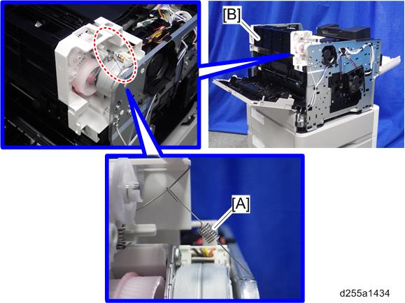
- Remove the spring [A] from the paper exit unit [B].
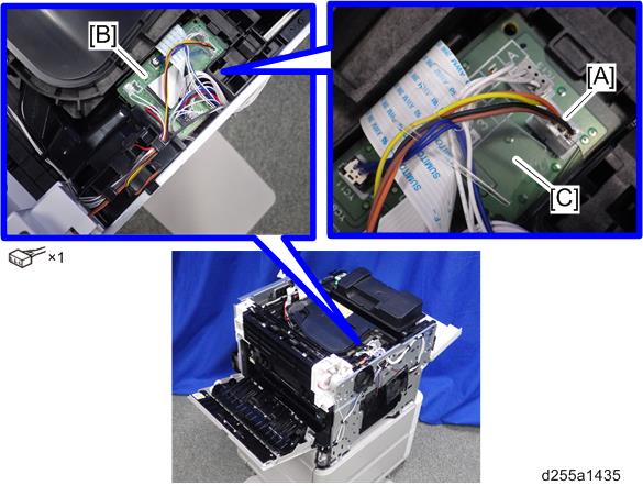
- Disconnect the connector [A] from the Connect-Left PCB (PCB20) [B], and then release it from the plastic harness guide [C].
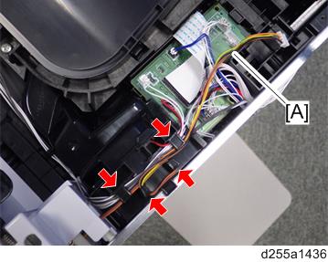
- Release the harness [A], disconnected in the previous step, from the harness guides.
- Remove the three screws from the left side of the machine.
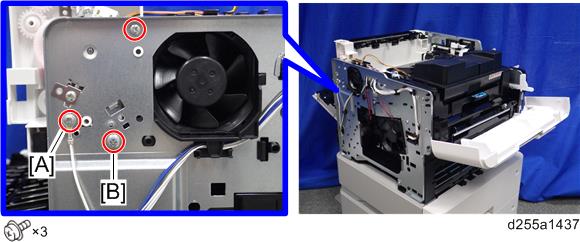

- The screw [A] is a ground screw and [B] is a big screw. Be careful not to use the wrong screws when installing the paper exit unit.
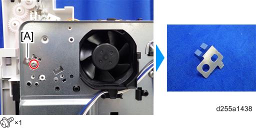
- Remove the bracket [A].
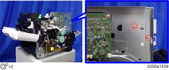
- Remove the two screws from the right side of the machine.
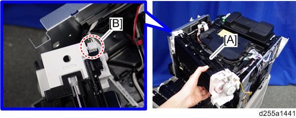
- Remove the paper exit unit [A].
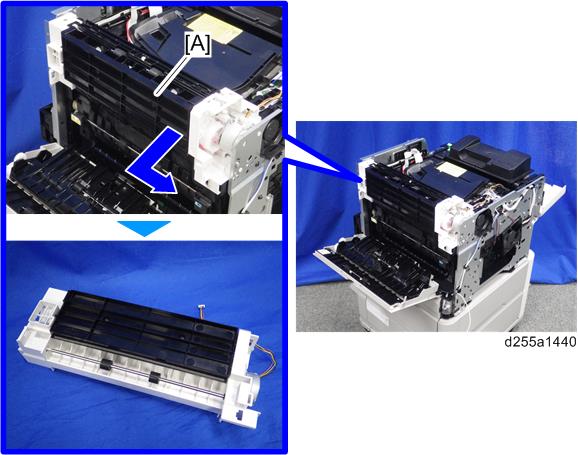
- When removing the paper exit unit [A], release the four hooks from both sides of the paper exit unit.
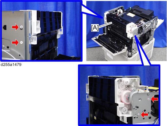
- When removing the paper exit unit [A], disconnect the connector [B] from the paper exit unit.
- When removing the paper exit unit [A], release the four hooks from both sides of the paper exit unit.