
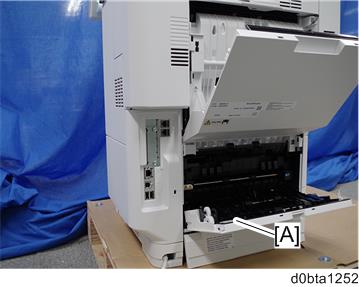
Turn OFF the main power, and unplug the machine power cord before starting the following procedure.
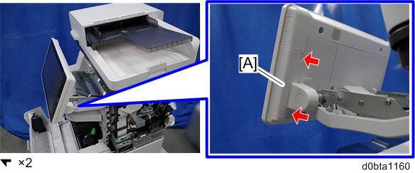
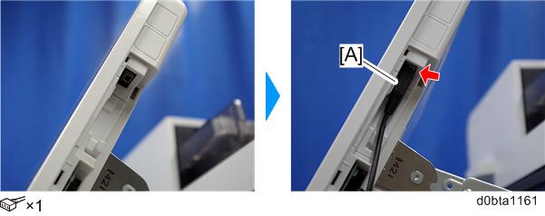
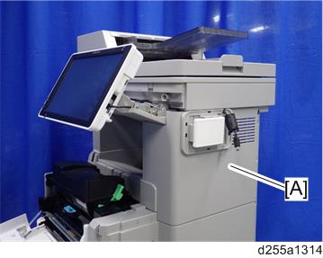
- Open the rear upper cover [A].
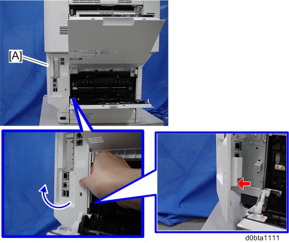
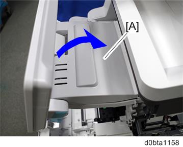
Release the hook by opening the right side of the cover, and then remove the cover [A] by rotating it in the direction of the blue arrow.

- Be careful not to damage the hooks on the inside of the controller cover when you remove or install the controller cover.
- Be careful not to damage the hooks on the inside of the controller cover when you remove or install the controller cover.
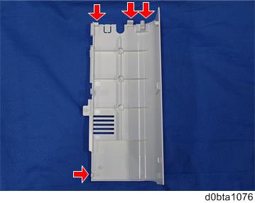
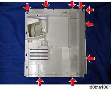
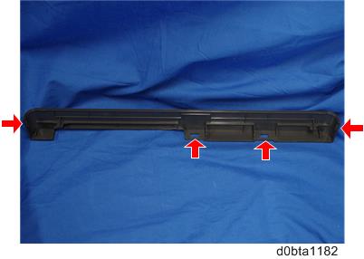
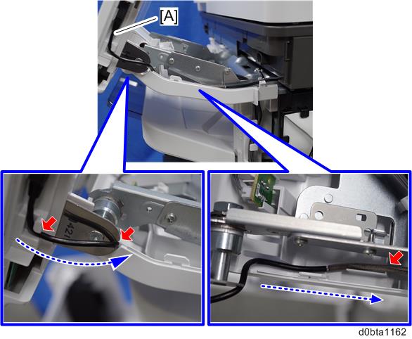
Insert a flathead screwdriver in the order of
 ,
,  , and
, and  to release the three hooks of the rear right stay [A].
Release the hook
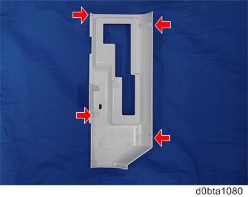
 and remove the rear right stay [A].
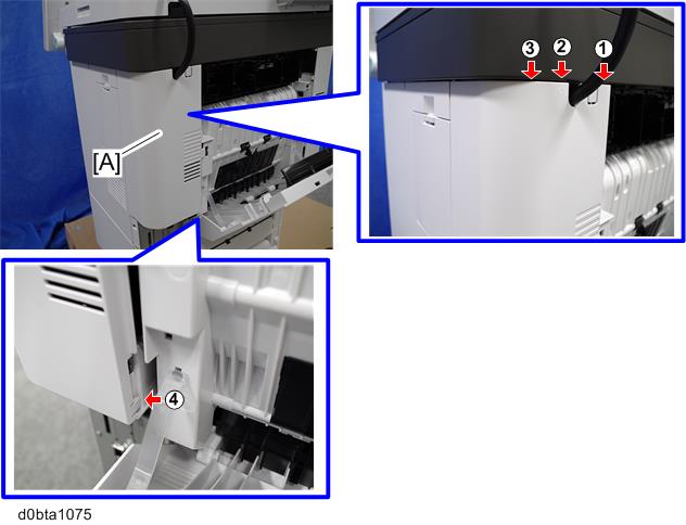
- Be careful not to damage the hooks on the inside of the rear right stay when you remove or install the rear right stay.
- Be careful not to damage the hooks on the inside of the rear right stay when you remove or install the rear right stay.
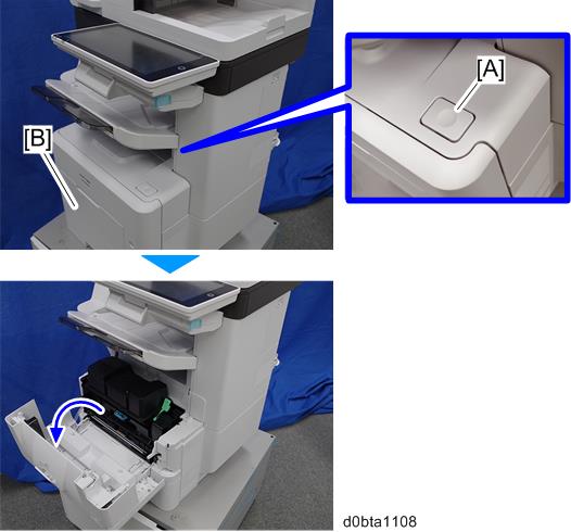
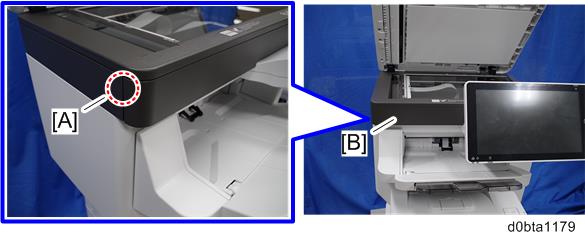
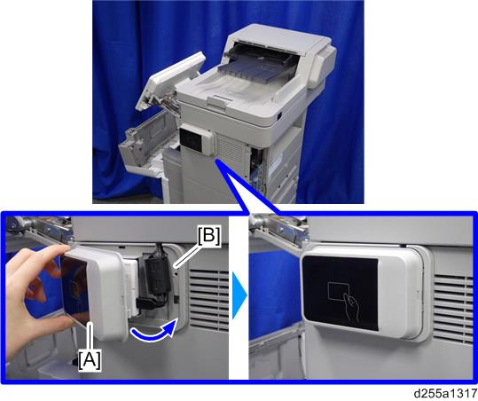
Push the button [A] and open the front cover [B].
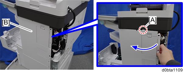
Release the hook [A] of the right upper cover [B] by opening the cover in the direction of the arrow.
Release the hooks [A] of the right upper cover [B] by lifting the bottom right of the cover, and then remove the cover.
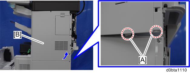
- Be careful not to damage the hooks on the inside of the right upper cover when you remove or install the right upper cover.
- Be careful not to damage the hooks on the inside of the right upper cover when you remove or install the right upper cover.
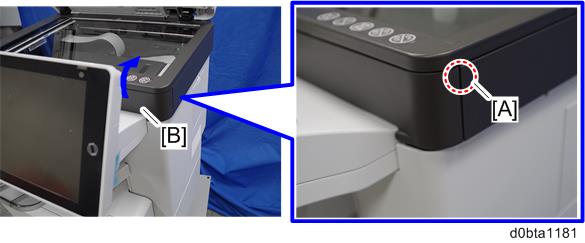
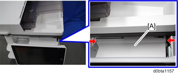
- Insert a flathead screwdriver at [A] to release the hook of the scanner front cover [B].
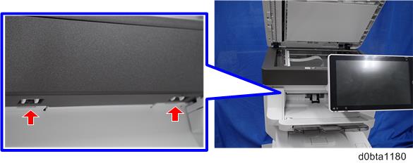
- Release the two hooks of the scanner front cover [A].
Insert a flathead screwdriver at [A] to release the hook, and then remove the scanner front cover [B].
- Be careful not to damage the hooks on the inside of the scanner front cover when you remove or install the scanner front cover.
- Be careful not to damage the hooks on the inside of the scanner front cover when you remove or install the scanner front cover.
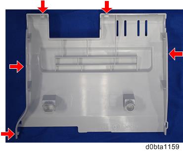
- Release the two hooks of the operation panel arm upper cover [A].
Remove the operation panel arm upper cover [B].
- Be careful not to damage the hooks on the inside of the operation panel arm upper cover when you remove or install the operation panel arm upper cover.
- Be careful not to damage the hooks on the inside of the operation panel arm upper cover when you remove or install the operation panel arm upper cover.
- Remove the hinge cover [A] from the operation panel.
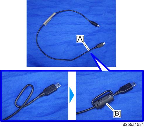
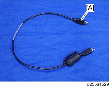
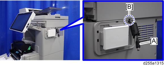
Make a loop at the end of the USB cable [A], and then attach the ferrite core [B], as shown below.
- Attach the ferrite core at a distance of 4.0 cm (1.6 inch) [A] from the end of USB cable.
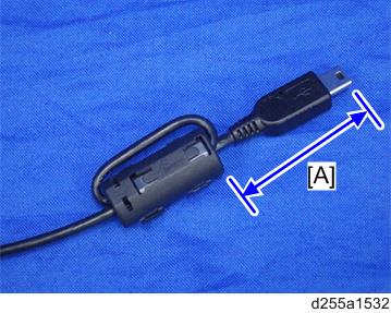
- Attach the ferrite core at a distance of 4.0 cm (1.6 inch) [A] from the end of USB cable.
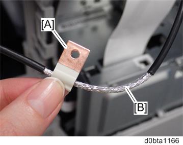
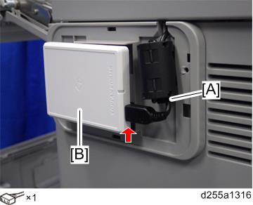
- Peel off the conductive tape [A] from the USB cable [B].
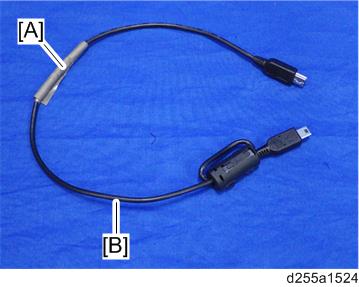
Insert the USB cable [A] into the USB connector of the operation panel.
- Insert the end [A] of the USB cable, where the ferrite core is not attached, into the media slot of the operation panel.
- Insert the end [A] of the USB cable, where the ferrite core is not attached, into the media slot of the operation panel.
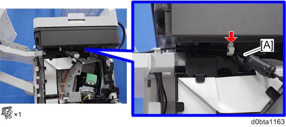
- Route the USB cable [A] to the right side of the machine.
- Secure the USB cable [A] with the clamp.
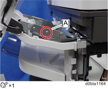
- Remove the screw [A] from the operation panel arm.
Install the FG clamp [A] to the operation panel arm.
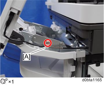
- When installing the FG clamp, bind the USB cable [B] with the FG clamp [A]. Make sure to bind the part where the coating is stripped partially.
- When installing the FG clamp [A], use the screw provided with NFC Card Reader Type M24.
- When installing the FG clamp, bind the USB cable [B] with the FG clamp [A]. Make sure to bind the part where the coating is stripped partially.
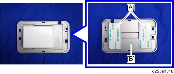
- Attach the hook and loop fastener [A] to the base cover [B] at the position shown below.
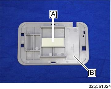
Peel off the mount from the hook and loop fastener, and then attach the NFC card reader [A] to the base cover [B] at the position shown below.
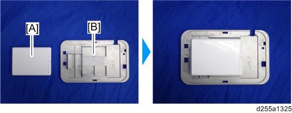
- Attach the NFC card reader with the USB port [A] of the NFC card reader set to face right.
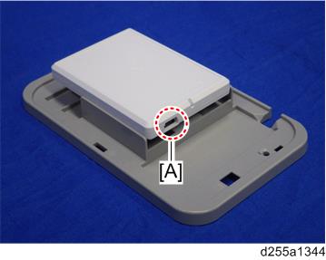
- Attach the NFC card reader with the USB port [A] of the NFC card reader set to face right.
- Peel off the mount [A] of the seal from the back side [B] of the base cover.
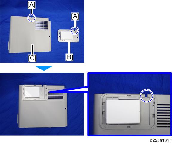
- Fit the notch part [A] of the base cover [B] into the right upper cover [C] of the main machine, and then attach it.
Reattach the right upper cover [A] to the main machine.
- When attaching the right upper cover, pull out the USB cable [A] through the notch [B] in the right upper cover.
- When attaching the right upper cover, pull out the USB cable [A] through the notch [B] in the right upper cover.
- Connect the USB cable [A] to the NFC card reader [B].
- Attach the upper cover [A] to the base cover [B].
- Reassemble the machine.