
- Turn OFF the main power, and unplug the machine power cord before starting the following procedure.
- You need two or more persons to lift the main machine. The main machine is highly unstable when it is lifted by one person and may cause injury or property damage.
- Be sure to hold the specified positions when lifting the machine.
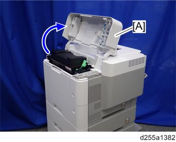
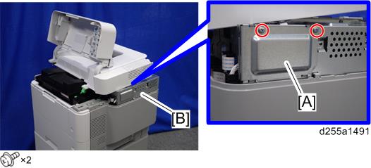
- Open the upper cover [A].
Remove the two screws from the upper cover [A].
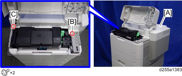

- The screw [B] is a sems screw. The screw [C] is a tapping screw. Be careful do not use the wrong screws when installing the upper cover.
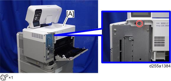
- Remove the screw from the rear side of the upper cover [A].
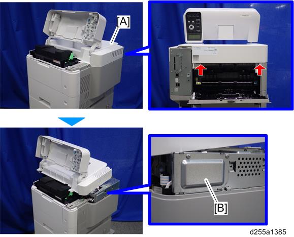
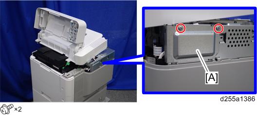
- Lift the upper cover [A] by releasing the two hooks, and then put it on the mainframe so that you can access the bracket [B] on the right side of the machine.
- Remove the bracket [A].
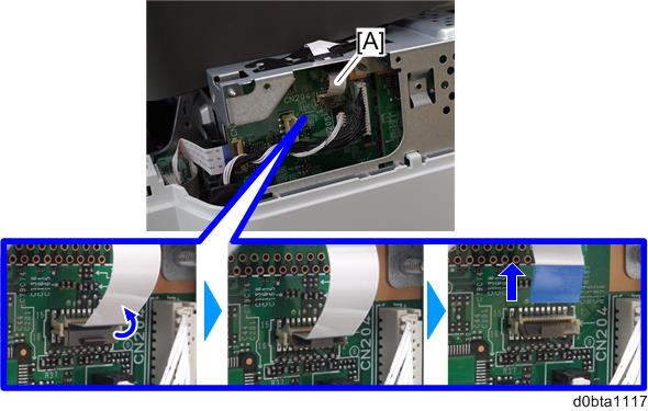
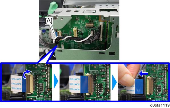
Disconnect the flat cable from the BiCU [A].
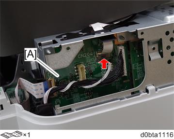
- Make sure to open the flap before disconnecting the flat cable [A], as shown in the following pictures. Otherwise, the connector may be damaged.
- Make sure to open the flap before disconnecting the flat cable [A], as shown in the following pictures. Otherwise, the connector may be damaged.
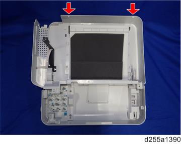
Remove the plastic sheet [A] from the mainframe (hook×2), and then remove the upper cover [B].
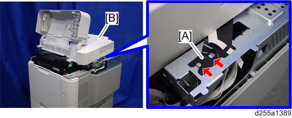
- Be careful not to damage the hooks on the inside of the upper cover when you remove or install the upper cover.
- Be careful not to damage the hooks on the inside of the upper cover when you remove or install the upper cover.
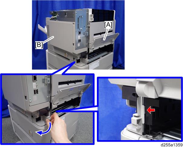
- Remove the paper feed tray [A] by pulling it out.
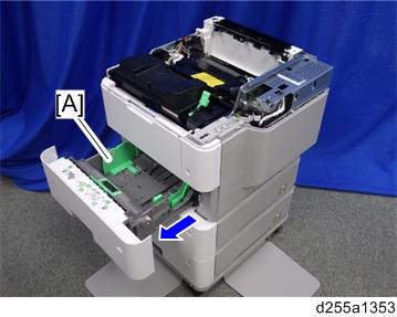
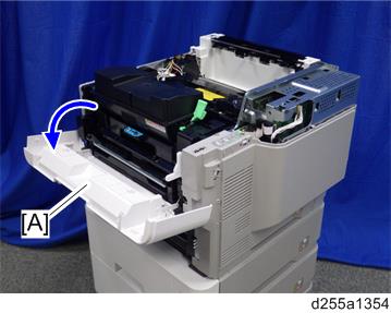
- Open the front cover [A].
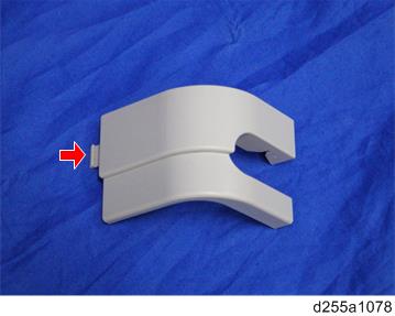
Remove the power connector cover [A].
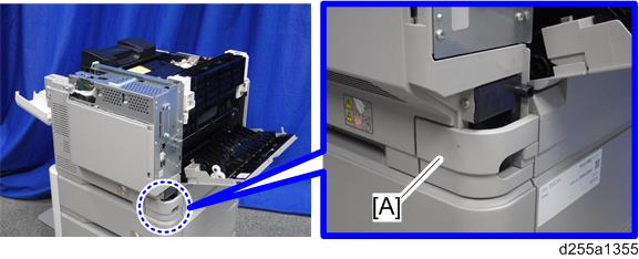
- When removing the power connector cover, pull it in the direction of the arrow.
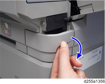
- Be careful not to damage the hook on the power connector cover when you remove or install the power connector cover.
- When removing the power connector cover, pull it in the direction of the arrow.
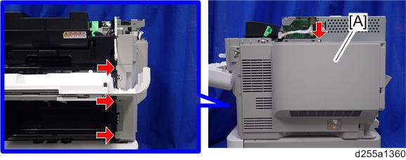
Remove the five screws from the right cover [A].
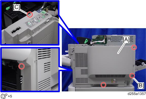
- The screw [B] is a tapping screw. The screw [C] is a long screw. Be careful not to use the wrong screws when installing the right cover.
- Close the rear upper cover [A].
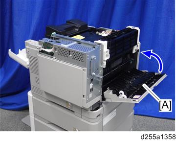
- Open the rear lower cover [A], and then release the hook of the right cover [B] by rotating it in the direction of the blue arrow.
Release the four hooks, and then remove the right cover [A].
- Be careful not to damage the hooks on the inside of the right cover when you remove or install the right cover.
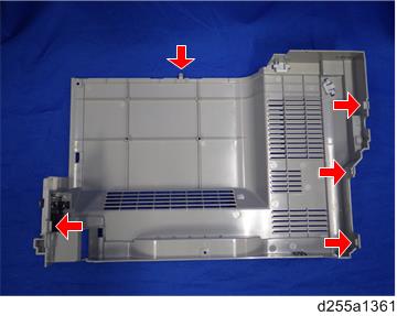
- Be careful not to damage the hooks on the inside of the right cover when you remove or install the right cover.
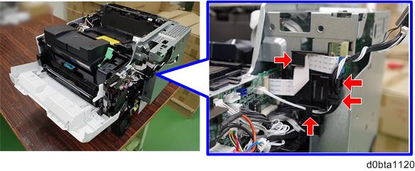
Disconnect the flat cable and two connectors.
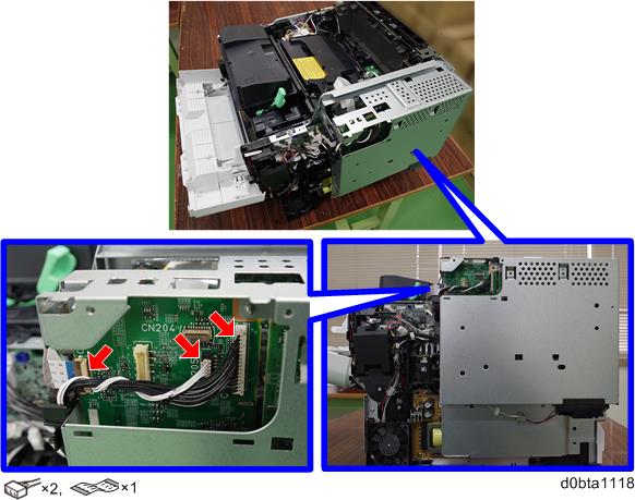
- Make sure to open the flap before disconnecting the flat cable [A] as shown in the following pictures. Otherwise, the connector may be damaged.
- Make sure to open the flap before disconnecting the flat cable [A] as shown in the following pictures. Otherwise, the connector may be damaged.
- Release the flat cable and harness from the harness guides.
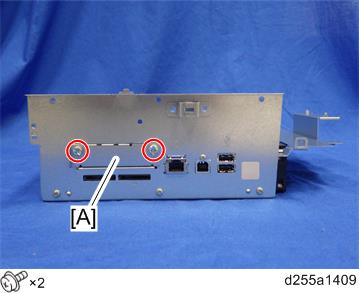
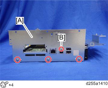
Remove the seven screws from the controller box [A].
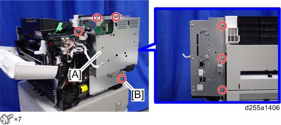
- The screw [B] is a tapping screw. Be careful not to use the wrong screws when installing the controller box.
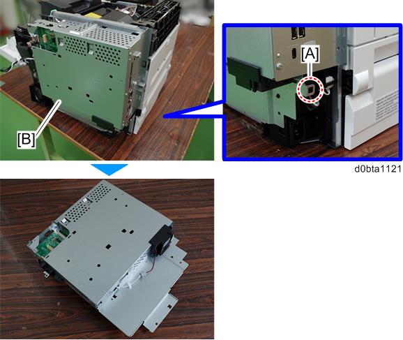
- Release the hook [A], and then remove the controller box [B].
- Remove the slot cover [A].
Remove the controller box cover [A].
- The screw [B] is a small screw. Be careful not to use the wrong screw when installing the controller box cover.
Remove the controller board [A] with the BiCU [B].
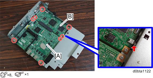
- Be careful not to damage the backside of the controller board [A] and the BiCU [B].
Connect the two cables [A] to the HDD [B].
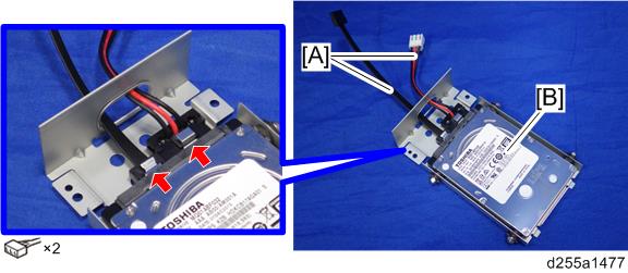
- Make sure to pass the cables through the hole [A] of the HDD bracket.
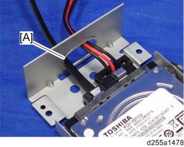
- Make sure to pass the cables through the hole [A] of the HDD bracket.
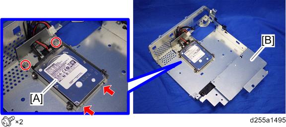
- Install the HDD [A] on the controller box [B] with the tapping screws. (hook×2)
Reassemble the machine.
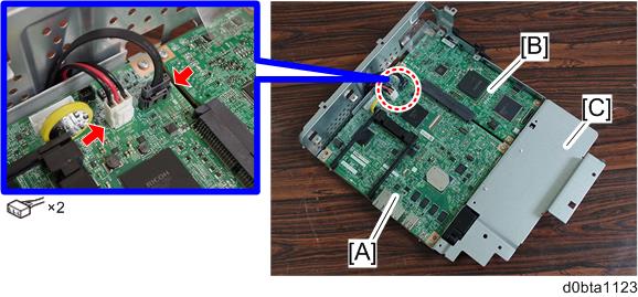
- When reattaching the controller board [A] with the BiCU [B] on the controller box [C], connect the two cables of the HDD to the controller board [A].
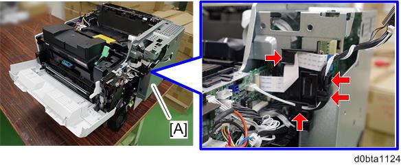
- When reattaching the controller box [A], make sure to secure the harness and flat cable to the harness guides, as shown below.
- When reattaching the bracket [A] of the controller box [B], do not interpose harness and flat cable between bracket and controller box.
- When reattaching the controller board [A] with the BiCU [B] on the controller box [C], connect the two cables of the HDD to the controller board [A].