
Turn OFF the main power, and unplug the machine power cord before starting the following procedure.
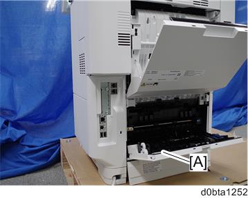
- Open the rear upper cover [A].
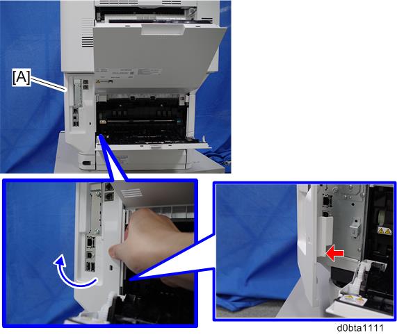
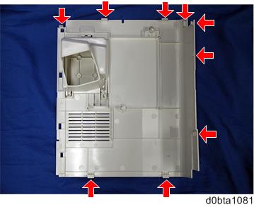
Release the hook by opening the right side of the cover, and then remove the cover [A] by rotating it in the direction of the blue arrow.

- Be careful not to damage the hooks on the inside of the controller cover when you remove or install the controller cover.
- Be careful not to damage the hooks on the inside of the controller cover when you remove or install the controller cover.
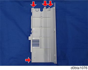
Insert a flathead screwdriver in the order of
 ,
,  , and
, and  to release the three hooks of the rear right stay [A].
Release the hook
 and remove the rear right stay [A].
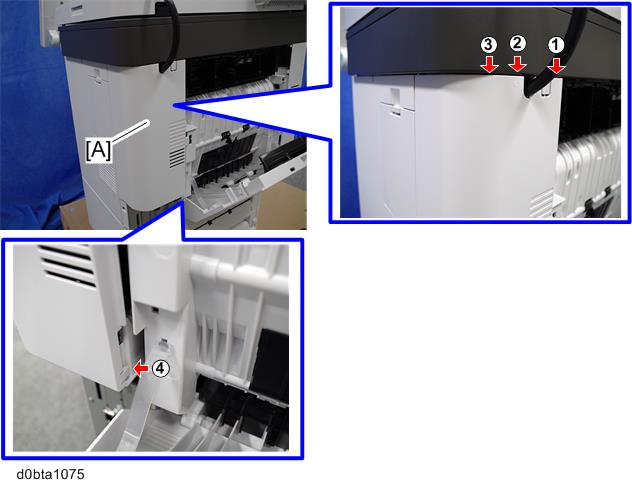
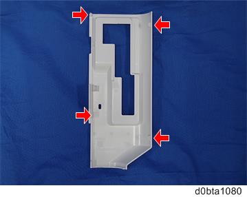
- Be careful not to damage the hooks on the inside of the rear right stay when you remove or install the rear right stay.
- Be careful not to damage the hooks on the inside of the rear right stay when you remove or install the rear right stay.
Push the button [A] and open the front cover [B].
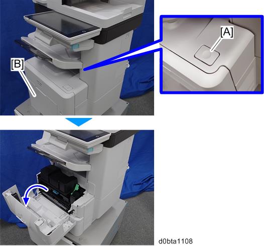
Release the hook [A] of the right upper cover [B] by opening the cover in the direction of the arrow.
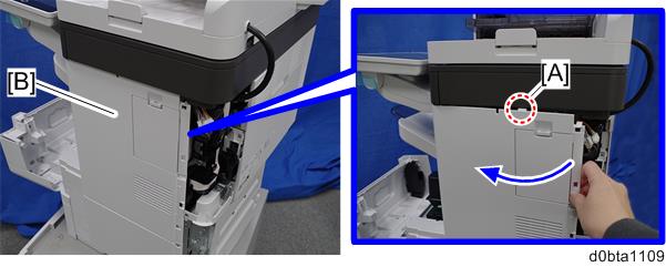
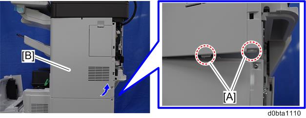
Release the hooks [A] of the right upper cover [B] by lifting the bottom right of the cover, and then remove the cover.
- Be careful not to damage the hooks on the inside of the right upper cover when you remove or install the right upper cover.
- Be careful not to damage the hooks on the inside of the right upper cover when you remove or install the right upper cover.
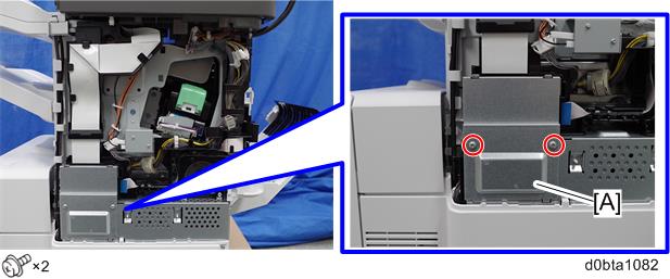
Remove the bracket [A].
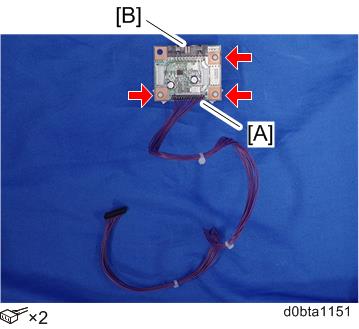
Connect the harness (13 pins) to CN3 [A] and connect the harness from the optional counter device to CN4 [B] on the optional counter interface board. Then, install three plastic standoffs as shown below. Do not install the stud stay in the top left hole.
Install the three plastic standoffs in the three holes of the mainframe.
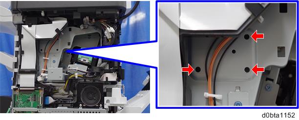
Pass the harness through the holes [A] and [B], and then connect the other end to CN112 [C] on the BiCU.
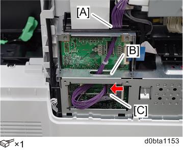
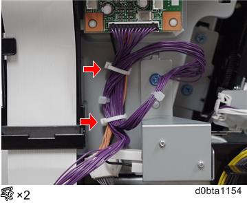
Clamp the harness using the clamps installed in the mainframe.
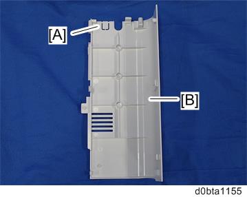
Remove the knockout [A] of the rear right stay [B] with a pair of nippers.
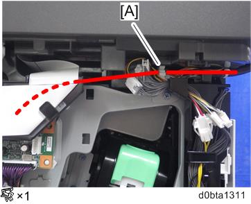
- Route the harness of the optional counter device as shown below, clamp it with the existing clamp [A], and pass it through the rear right stay using the hole opened in step 13.
Reassemble the machine.