
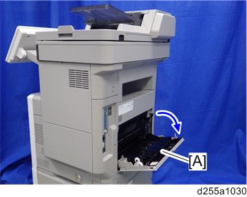
- Turn OFF the main power, and unplug the machine power cord before starting the following procedure.
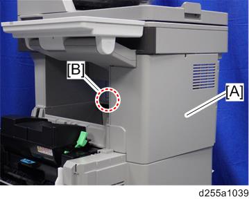
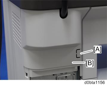
- Open the rear upper cover [A].
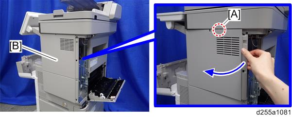
- Insert a flathead screwdriver into [A] to release the hook on the inside of the controller cover [B].
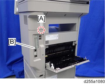
Release the hook by opening the right side of the cover, and then remove the cover [A] by rotating it in the direction of the blue arrow.
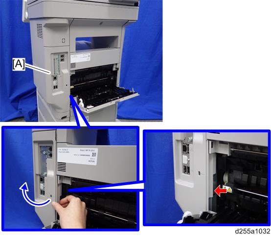

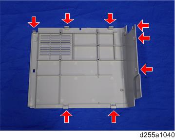
- Be careful not to damage the hooks on the inside of the controller cover when you remove or install the controller cover.
- Be careful not to damage the hooks on the inside of the controller cover when you remove or install the controller cover.
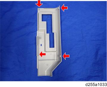
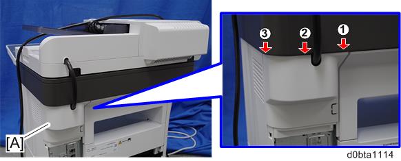
- Insert a flathead screwdriver in the order of
 ,
,  and
and  to release the three hooks of the rear left stay [A].
 Remove the rear right stay [A].
- Be careful not to damage the hooks on the inside of the rear left stay when you remove or install the rear right stay.
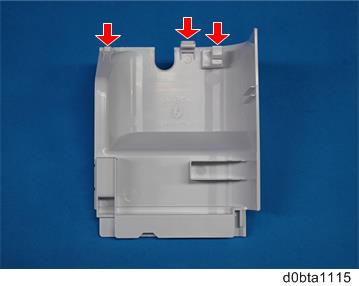
- Be careful not to damage the hooks on the inside of the rear left stay when you remove or install the rear right stay.
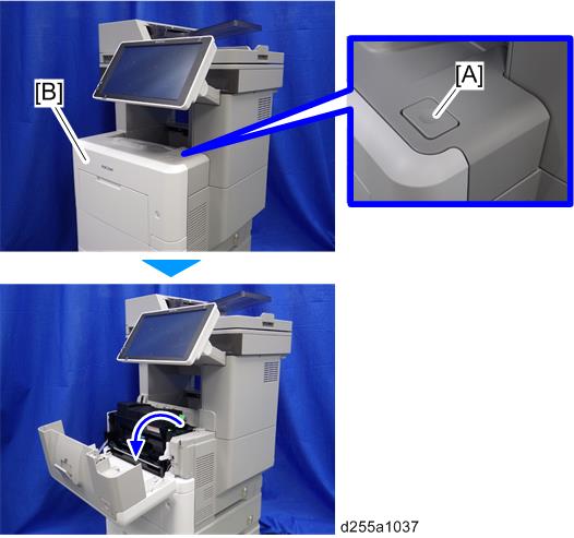
- Push the button [A] and open the front cover [B].
- Release the hook [A] of the right upper cover [B] by opening the cover in the direction of the arrow.
Remove the right upper cover [A] by inserting a flathead screwdriver into [B].
- Be careful not to damage the hooks on the inside of the right upper cover when you remove or install the right upper cover.
- Be careful not to damage the hooks on the inside of the right upper cover when you remove or install the right upper cover.
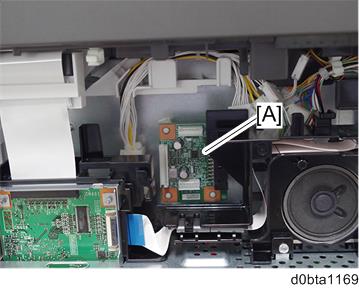
- Remove the bracket [A].
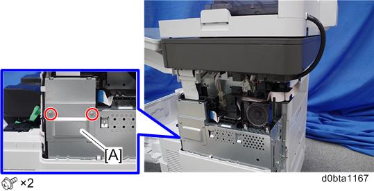
- Install the four stud stays as shown below.
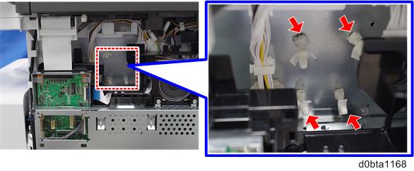
- Install the optional counter interface board [A] on the four stud stays.
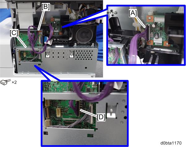
- Connect the harness (13 pins) to CN3 [A] on the optional counter interface board.
- Pass the harness through the holes [B] and [C], and then connect the other end to CN112 [D] on the BiCU.
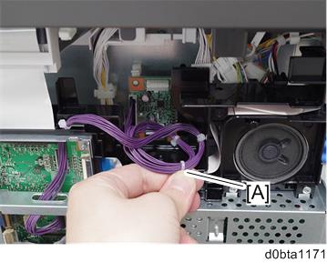
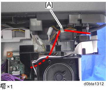
- Bind the harness with the harness bind [A] as shown below.
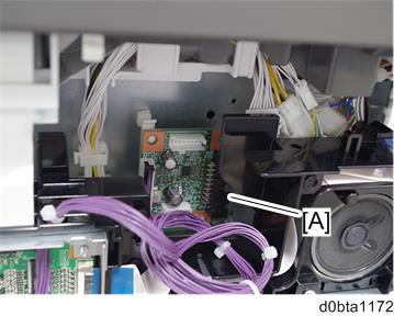
- Connect the harness from the optional counter device to CN4 [A] on the optional counter interface board.
- Remove the knockout [A] of the rear right stay [B] with a pair of nippers. Then pass the harness which is connected to the optional counter interface in the previous step.
- Route the harness of the optional counter device as shown below, clamp it with the existing clamp [A], and pass it through the rear right stay using the hole opened in step 16.
- Reassemble the machine.