Symptom
The following occur:
| SC672-00 | Communication error between operation panel and controller board (PCB15) after machine is powered on. |
| SC672-10 | Communication error (receive) between operation panel and controller board (PCB15) after machine is powered on. |
| SC672-11 | Communication error (send) between operation panel and controller board (PCB15) after machine is powered on. |
| SC672-12 | Communication error between operation panel and controller board (PCB15) after normal start-up. |
| SC672-13 | Communication error between operation panel and controller board (PCB15) after normal start-up; Operation panel not detected. |

- SC672 does not appear on the SMC report, as it is not logged.
- The Smart Operation Panel communicates with the controller via a USB cable and BiCU (PCB16). SC672 is triggered when the panel cannot communicate with the controller.
Cause
Possible causes of SC672 include:
- USB communication path failure (USB cable, BiCU (PCB16))
- Controller board (PCB15) boot up error and/or operation panel boot up error due to abnormal break in operations of Controller board (PCB15).
Possible causes of operation panel cannot light include:
- USB communication path failure (USB cable, BiCU (PCB16))
- Operation panel cannot communicate with controller board (PCB15) due to controller board (PCB15) boot-up error
Solution
Do the following.
- Turn the machine power OFF/ON.
- Do the action in the flowchart below to determine the cause and best course of action when SC672 occurs.
If the SC recurs after you do the action in this flowchart, do the following.
- If SC819 (cache error) appears in the SC history, replace the controller board (PCB15).
- If SC991 (SCS: scs time count level c’) appears in the SC history, replace the controller board (PCB15) and USB cable.
Flowchart to determine parts to replace when SC672 occurs
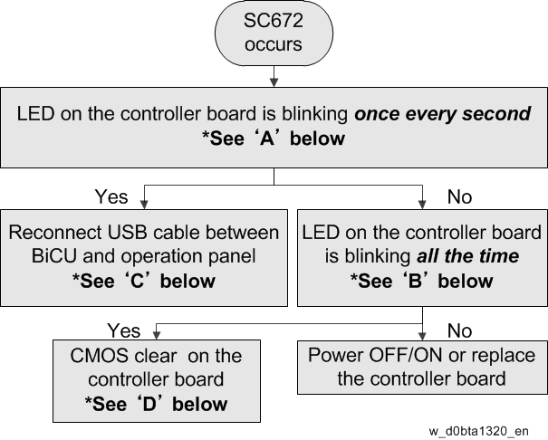
| Parts | How to determine the cause |
|---|---|
| USB cable | LED on controller board (PCB15) blinks once every second |
| Operation panel | LED on controller board (PCB15) blinks once every second |
| Controller board (PCB15) | LEDs on Controller board (PCB15) blink constantly |
Flowchart to determine parts to replace when no display on operation panel
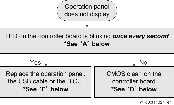
| Parts | How to determine the cause |
|---|---|
| USB cable | LED on controller board (PCB15) blinks once every second |
| Operation panel | LED on controller board (PCB15) blinks once every second |
| BiCU (PCB16) | - |
| Controller board (PCB15) | LED on Controller board (PCB15) does not blink |
[A]: LEDs on the controller board (PCB15)
Check the condition (lit, off, blinking) of the LED on the controller board (PCB15).
Normal situation: POSTCODE LED 8 [A] and BIOS LED [B] blinking once every second.

| No. | Note |
|---|---|
| LED | For CPU
|
Confirmation procedure:
- Remove the FCU unit. (Refer to FAX unit FSM.)
- Remove the I/F slot.
- Turn On the machine and check the LED from the rear-right side of the machine.
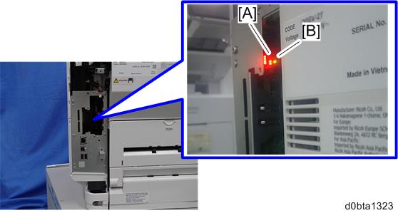
[A]: POSTCODE LED8
[B]: BIOS LED
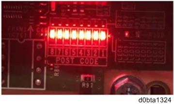
[B]: Abnormal mode: LEDs on the controller board (PCB15)
LEDs 1 to 8 blink constantly.
Example:
| No. | Note |
|---|---|
| POSTCODE 1-8 | 1. For self-diagnosis code (BIOS). 2. After the BIOS starts up, LEDs 4,5,7 turn off and LEDs 1,2,3 ,6 turn on and LED 8 blinks. LED 8 is lit or off when there is a problem with the CPU. |
| BIOS LED |
|
[C]: Reconnecting and replacing the USB cable
Reconnecting the USB cable
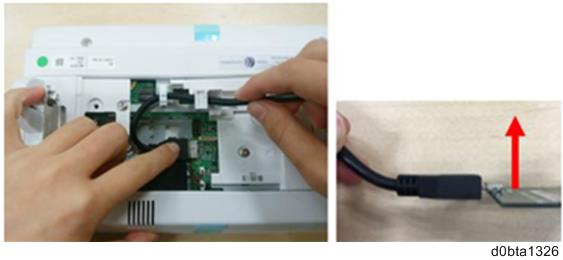
USB connector at the operation panel: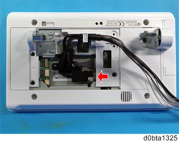
When connecting the cable, hold the molded part of the cable as shown below so as not to apply excessive force on the connector part. Applying excessive force toward the upper direction on the connector may cause connection failure.
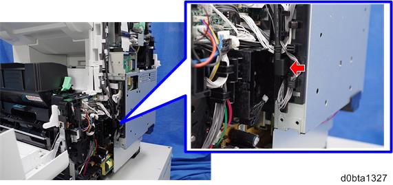
USB connector at the BiCU (PCB16):
Replacing the USB cable
Refer to "Operation Panel Unit".
[D]: CMOS clear
- Turn the machine power OFF.
- Turn Dip switch 1-3 ON for 10 seconds.
- Turn Dip switch 1-3 OFF.
- Turn the machine power ON.
Dip switch on the controller board (PCB15):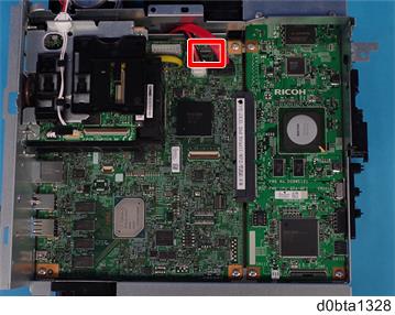
[E]: Replacing the operation panel, the USB cable or the BiCU (PCB16)
Refer to "Operation Panel Unit" or "BiCU (PCB16)".