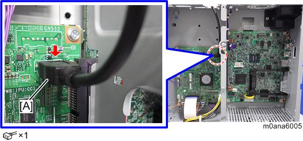
Re-connect the USB cable between the IPU board and the operation panel.
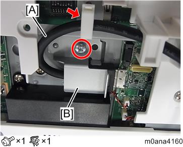
- Release the clamp, and then make the cable straight [A].
Remove the bracket [B].
Re-connect the USB cable between the IPU board and the operation panel.
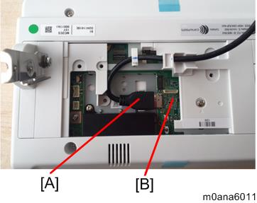
[A]: CABLE:USB3.0:AWG22:1600:ASS'Y
[B]: PCB:CHEETAHG2:NAIS:CO-P1.5:ASS'Y
When installing, attach the bracket [B] first, and then bend the cable [A] and secure it.
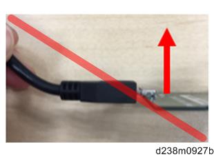
Do not apply excessive force on the connector part. Applying excessive upward force on the connector may cause connection failure.
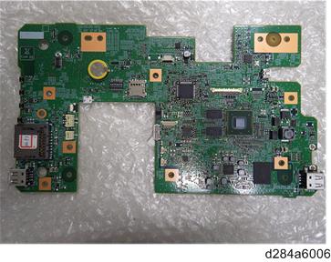
PCB for the operation panel
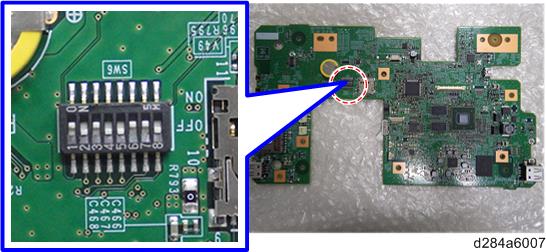
- 1, 3, 6, and 7 are ON for normal.
USB connector [A] (IPU)