- When installing this option, turn OFF the main power and unplug the power cord from the wall socket. If installing without turning OFF the main power, an electric shock or a malfunction may occur.
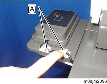
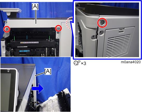
- Remove the small cover [A].
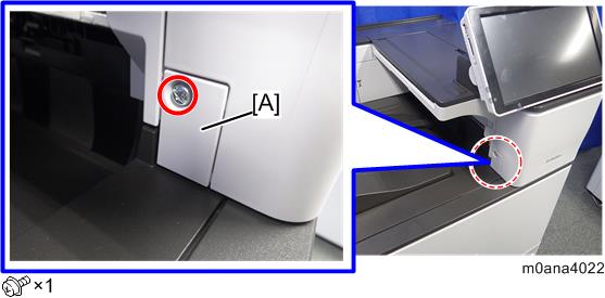
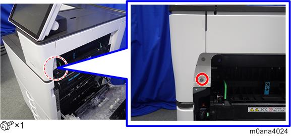
Open the right cover, then remove the screw.
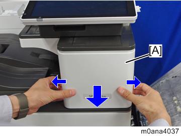
Release the hooks on the inside of the upper front cover [A] by pulling the cover's sides outward, and remove the upper front cover [A].
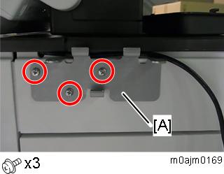
- Remove the right upper cover [A] as shown by the arrow.
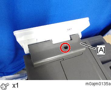
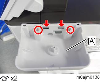
- Remove the operation panel upper cover [A].
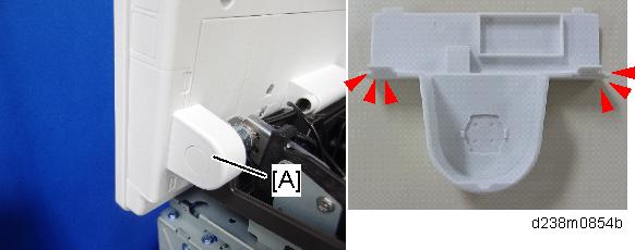
- Remove the operation panel right cover [A].
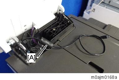
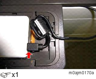
Connect the USB cable (800mm) to the machine’s operation panel connector.
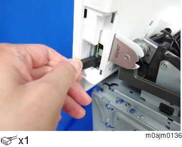
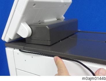
Pass the connector at the other end of the cable through the gap in the hinge.
If it is difficult to pass the cable through, loosen the two screws of the hinge to widen the gap. After passing the USB cable through, fasten the screws again.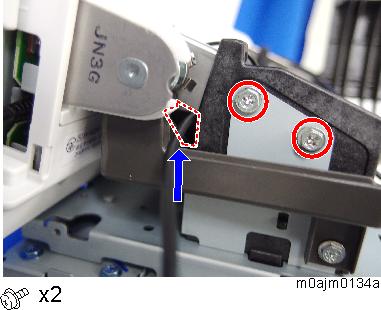
Make a single loop in the part of the cable which has passed through the gap in the hinge, and attach the ferrite core [A] to it.
- Reattach the operation panel right cover.
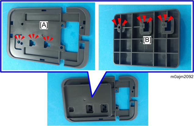
When reattaching the cover, pass the USB cable through the U-shaped groove [A] at the hinge of the operation panel and notch [B] on the cover under the cover.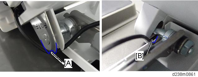
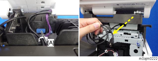
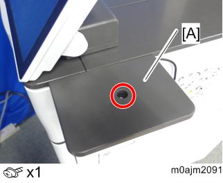
- Pass the USB cable through the hole at the front [A].
Reattach the operation panel upper cover.

Depending on the part where the NFC reader is attached, store the surplus part of the USB cable under the operation panel upper cover.
Store the ferrite core behind the operation panel upper cover as shown below:
When attaching the cover, be careful not to trap the USB cable or harness between the covers.
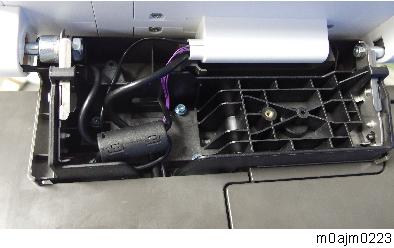
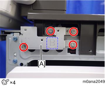
- Attach Bracket B [A] to the machine’s right frame (M3x8).
Thread holes in the removed right upper cover (3 points).

Using the supplied tapping screw (M5x13) [A], position the screw at the center part of the guide rib and thread each hole. After threading each hole, use a tool such as a screwdriver to enlarge the hole so that the fastening screw (M3x20) can go through it.
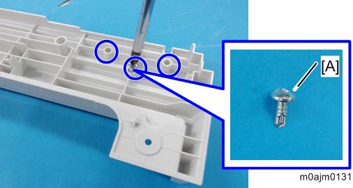
- Be careful not to drop the shavings into the machine (do not leave shavings around the holes).
- Reattach the covers in the following order: right upper cover [A], upper front cover [B], small cover.
When attaching the right upper cover, pass the USB cable through the notch [C] in the right upper cover.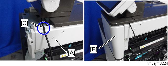
- Pass the USB cable through the groove in the cover.
Attach the bracket for side table [A] to the right upper cover (M3x20).
- Attach the lower cover [A] by engaging it with the two tabs on Bracket B (M3x8).
Attach the upper cover [A] (M3x10).
Attach the reader spacer [B] to the reader holder [A].
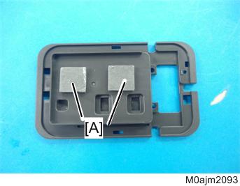
Attach the sponge cushions [A] to two points on the reader spacer as shown.
- Make a single loop in the USB cable, and then attach the ferrite core [A].
Attach the ferrite core to the cable 45 mm away from the cable end.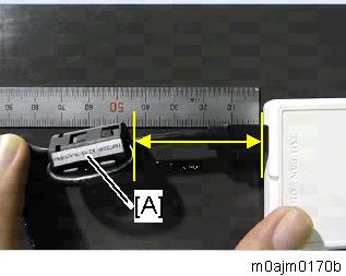
- Connect the USB cable to the NFC reader.
- Place the NFC reader [A] on the spacer [B], and then attach the reader cover [C].
Be careful not to trap the USB cable between the covers.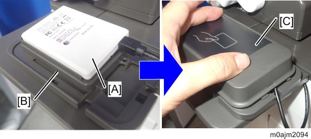
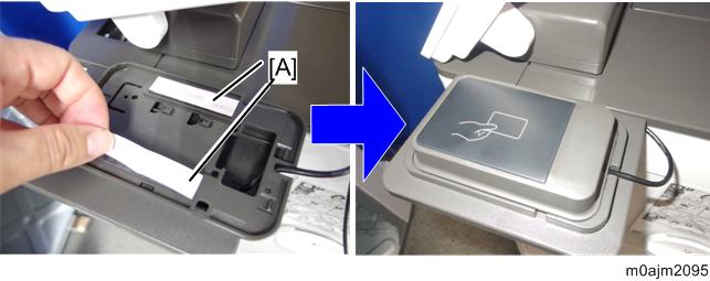
- Remove the release paper [A] at the back of the reader holder, and then secure the NFC reader on the table.
- As required, use the stick-type clamps [A] to secure the USB cable.