- When installing this option, turn OFF the main power and unplug the power cord from the wall socket. If installing without turning OFF the main power, an electric shock or a malfunction may occur.
- This option cannot be used together with the following peripherals:
- Internal Shift Tray SH3070 (D691)
- Side Tray Type M3 (D725)
- Internal Finisher SR 3180 (D766)
- Bridge Unit BU3070 (D685)
- Internal Multi-Fold Unit FD3000 (D3E4) - To use together with the "1 Bin Tray BN3110 (D3CQ)", after attaching the bottom plate of this option, attach the "1 Bin Tray BN3110 (D3CQ)", and then install this option.
- To use together with the "Punch Unit PU3040 (D716)", first attach the "Punch Unit PU3040 (D716)" before installing this option.
- Remove the orange tape and shipping retainers.
- Remove the package accessories (fixing screws, etc.).
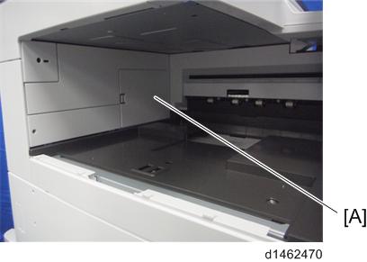
- Remove the paper exit tray [A].
- Remove the paper exit feeler [A].
- Tuck in the lever [A] for detecting when the tray is full.
- Open the front cover, and then remove the upper left cover [A] (
×1).
- Release the hooks [A], and remove the left rear cover [B].
- Remove the inverter tray [A], and the tray support plate [B] (
Open the right cover, and then remove the upper front cover [A].
- When removing the upper front cover, release the hooks at the back of the cover.
- Tilt the operation panel [B] upward to a horizontal position, and then remove the upper front cover [A].
- Remove the paper exit cover [A] (
- Remove the connector cover [A].
- Remove the paper exit lower cover [A].
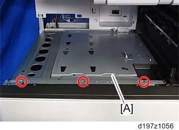
- Remove the fixing screws on the upper rear inner cover [A].
- Remove the upper rear inner cover [A].
- Install a screw removed in step 12 (
While pressing the bottom plate [A] into the area shown by the blue circle [B], insert it into the slot shown by the blue circles [C] and [D].
- The following procedure is the easiest way to set this component.
- 1) Slip the bottom plate [A] into the position in the blue circle [B].
- 2) Insert the bottom plate [A] into the hole in the blue circle [C].
- 3) When the bottom plate [A] is picked up (see below), it can be inserted into the hole in the blue circle [D].
Attach the bottom plate [A] (
Attach the upper rear inner cover.
Attach the paper exit cover.
Reattach the connector cover and the covers (removed in step 9 and step 10), and then close the right door.
Remove the driven roller [B] at the machine’s exit tray and attach the supplied driven roller [A].
- Insert a flathead screwdriver into the depression in the center, and then, lifting the driven roller, unlock the part indicated by the red arrow.
- When attaching the driven roller, push its center all the way in until it clicks.
[A]: The supplied driven roller has flat rollers.
[B]: The machine’s standard driven roller has drum-type rollers (as indicated by the red frames).Attach the paper support guide [A] (Tab x4).
- Up to this point, the procedure is the same as punch unit installation (for fitting the punch unit, refer to Step 3 and later of the punch unit installation procedure).
Slide the finisher front right cover [A] from left to right to attach it (
Reattach the inverter tray.
Attach the entrance guide plate [B] to the finisher [A] (
Slide the finisher [A] along the rail of the bottom plate from the left-hand side of the machine to attach it (
- Hold the front side [A] of the internal finisher as shown below to check if the internal finisher is correctly set in the rail of the bottom plate.
- Hold the front side [A] of the internal finisher as shown below to check if the internal finisher is correctly set in the rail of the bottom plate.
Reattach the left rear cover.
Insert the upper left cover [A] from the front, and slide it to reattach it (
Attach the stabilizers [A].
- Because the weight is biased to the left of the machine if the internal finisher is installed, stabilizers are required on the left side. Because they are included with the finisher, install these stabilizers at the same time as you install the internal finisher.
Connect the interface cable [A] to the machine.
- Move the stapler unit forward, then set the staple cartridge [A].
- Reinstall the stapler unit, and then turn ON the main power.
- Check that the finisher can be selected at the operation panel, and check the finisher operation. Also when the punch unit is installed, check the punching operation.