- When installing this option, turn OFF the main power and unplug the power cord from the wall socket. If installing without turning OFF the main power, an electric shock or a malfunction may occur.
- The bridge unit cannot be used together with the following peripherals:
- Internal Shift Tray SH3070 (D691)
- Side Tray Type M3 (D725)
- Internal Finisher SR 3180 (D766)
- Internal Finisher SR 3130 (D690)
- Internal Multi-fold Unit FD3000 (M482-17, -21) - To use together with the "1 Bin Tray BN3110 (D3CQ)", attach the "1 Bin Tray BN3110 (D3CQ)" first before installing the bridge unit.
- Remove the orange tapes, shipping retainers, and provided accessories (fixing screws, etc.).
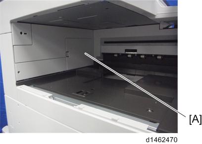
- Remove the paper exit tray [A].
- Remove the connector cover [A].
- Remove the paper exit feeler [A].
- Tuck in the lever [A] for detecting when the tray is full.
- Remove the driven roller [B] at the machine’s exit tray and attach the supplied driven roller [A].
- Insert a flathead screwdriver into the depression in the center, and then, lifting the driven roller, unlock the part indicated by the red arrow.
- When attaching the driven roller, push its center all the way in until it clicks.
[A]: The supplied driven roller has flat rollers.
[B]: The machine’s standard driven roller has drum-type rollers (as indicated by the red frames).
- Attach the paper support guide [A] (Tab x4).
- Open the front cover.
Remove the upper left cover [A] (
×1).
- The screw removed is used again in step 14.
Open the right cover, and then remove the upper front cover [A].
- When removing the upper front cover, release the hooks at the back of the cover.
- Tilt the operation panel [B] upward to a horizontal position, and then remove the upper front cover [A].
Attach the right front bracket [A].
- Attach the bridge unit to the machine (using the knob screw [A]).
- Attach the covers removed in step 9 and step 10, and then close the right cover.
- Attach the upper left cover [A] provided with the accessories.
- Attach the L type connecting bracket [A].
To fix the bridge unit securely on the machine, tighten the finisher's joint bracket [A] and the L type connecting bracket [B] together when installing the finisher. - Complete the bridge unit attachment. Refer to the procedure for connecting the optional unit downstream of the bridge unit.
- Booklet Finisher SR3240 (D3BB) (Booklet Finisher SR3240 / Finisher SR3230)
- Finisher SR3230 (D3BA) (Booklet Finisher SR3240 / Finisher SR3230)
- Booklet Finisher SR3220 (D3B9) (Booklet Finisher SR3220 (D3B9))
- Finisher SR3210 (D3B8) (Finisher SR3210 (D3B8))
- After the finisher is installed, turn ON the main power.
- Check that the finisher can be selected at the operation panel.