- Turn OFF the main power and unplug the power cord from the wall socket. If installing without turning OFF the main power, an electric shock or a malfunction may occur.
Remove the ADF and scanner unit
- Remove the left upper cover [A] (
× 1).
- Remove the rear cover [A].
- Open the right cover, and then remove the right cover [A] (
- Remove the front right cover [A] and the hinge cover [B].
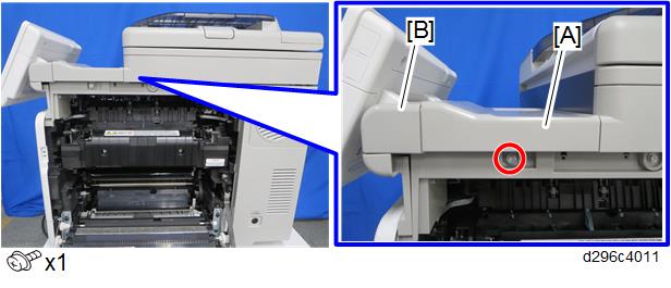
Remove the scanner rear cover [A] and scanner rear small cover [B].
Release two screws and three tabs for attaching the relay board [A] and FFC, to release the FFC.
Remove the FFC fixing bracket [A] on the back side of the FFC.
Remove the FFC fixing bracket while turning it counterclockwise and releasing the tab.
- Release the clamp for fixing the I/F cable [A].
- Remove the grounding plate [A].
Disconnect the FFC [A] from the relay board.
Disconnect the FFC for the relay board while pulling it out straight, because it does not have a lock mechanism.
Remove the harnesses and FFC from the scanner unit on the BiCU [A].
When lifting the scanner unit, move the harnesses out of the frame so that they do not interfere.
Disconnect the scanner FFC for the BiCU while pressing the lock release button.
- Remove the screws, and then remove the scanner unit [B] with the ADF [A].
Install the 1-bin Tray Unit
- Remove the orange tapes on the 1-bin tray unit.
- Remove the two clamps of the USB cable [A] of the control panel, bundle the excessive cable, and fasten with the clamps again.
- Attach the small frame [B].
Attach the mounting frame [A]. (M3×10:
- Install the screws in this order:
.
- Install the screws in this order:
- Route the USB cable [A] on the mounting frame and fasten with the two clamps.
- Attach the 1-bin tray unit [A]. (M3x10: 4 screw, and blue screw [D])
Fasten the grounding wire [B] included in this kit with one screw as shown below. Fasten the other end of the grounding wire with the screw [C]. - Connect the connector of the 1-bin tray unit to CN527 on the BiCU, and then fasten the harness [A].
Route the harness with the hook (marked by the dashed circle).
- Install the 1-bin tray [A].
Install the scanner unit [A] with the ADF.
When installing the scanner unit, make sure that the harnesses are not pinched between the scanner unit and the 1-bin tray unit (marked by the dashed circle).
- Attach the grounding plate [A] and clamp the harness [B] to the ADF. (Upper: blue screw ×1, Lower: M3x10 (existing))
Connect the relay board [A] and FFC [B].
Turn over twice to spread the FFC that was folded, and connect it.
Connect the FFC by pushing it straight, because it does not have a lock mechanism.
When reassembling, the FFC must be connected straight.
Attach the FFC fixing bracket [A].
Attach the relay board [B] with the three hooks [A] on the FFC fixing bracket.
Attach the FFC with the screw [C].
Set two ferrite cores [B] in the ferrite core holder [A] included in this kit.
Route the FFC of the scanner unit through the two ferrite cores in step 15.
Align the ferrite core holder [A] with the reference ribs on the back of the unit, and attach it with double-sided tape.- Route the FFC [A] in step 16 through one ferrite core [B] attached to the control box, and connect it to the BiCU.
- The FFC should be routed under the USB cable.
Do not connect the FFC at an angle. Otherwise, the scanner unit may be damaged.
Connect the scanner FFC for the BiCU while pressing the lock release button.
- Attach the following items:
- Hinge cover [A]
- Front right cover [B] (from the accessories, not the original cover)
- Attach the following items:
- Right rear cover [A] (from the accessories)
- Rear upper cover [B] (from the accessories)
- Left upper cover [C] (from the accessories, not the original cover)
- Attach the following items:
- Scanner rear small cover
- Scanner rear cover
- Right rear cover
- Rear cover
- Turn ON the main power and check the 1-bin tray unit operation.