Remove the upper right cover. (Upper Right Cover)
Remove the upper left cover. (Upper Left Cover)
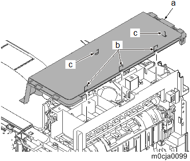
Lift up the machine rear side to remove the hook and then remove the upper cover (a).
When reattaching the top cover (a), apply two hooks (c). Press the machine rear side and apply three hooks (b).
Disconnect the FFC (a) from the connector (b) of the main/engine PCB (PCB1) and pull it out from the opening (c).
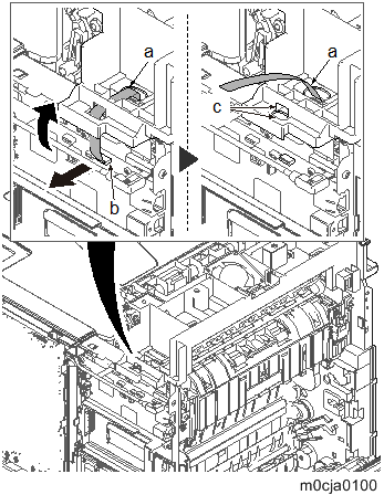
Disconnect the connector (a) of the exit fan motor (FAN7) and release the wire (b) from five hooks (c).
Disconnect the connector (a) of the duplex fan motor (FAN2) and release the wire (b) from two hooks (c).
Remove four screws (a)(M3x8).
Lift up the upper stay unit (b), and detach it.
*: Secure the screws in the order of the numbers when reattaching it.Remove the fusing wire cover [A].
Disconnect the connector (b) of the paper exit PCB (PCB8) (a).
Detach the exit unit (a).
When reattaching the exit unit (a), insert the gear shaft (b) into the hole on the side plate and two positioning pins (c) into the holes.
Then, insert the projections (e) into two square holes (d).