When you replace the FCU board, transfer the SRAM data from the old FCU board to the new FCU board. Do the following procedure to back up the SRAM data.
- The following data can be transferred: TTI, RTI, CSI, Fax bit switch settings, RAM address settings, NCU parameter settings.
- Remove the G3 Unit and disconnect the FFC connection. (See the installation in G3 Interface Unit Type M29 (D3DX-05, -06, -07, -13))
Check "LINE2" to see if the G3 unit is installed.
G3 Unit Installed | No G3 Unit Installed |
|---|---|
- Remove the controller box cover [A].
- Remove the interface slot cover [A].
- Remove the rear cover [A].
- Remove the controller box cover [A].
Red circle: remove
Blue circle: loosen - If the optional G3 interface unit is installed, remove the FFC from the FCU.
- Pull out the FCU [A] from the interface slot.
- Remove the slot cover [A].
- Change the orientation of the battery jumper switch [A] on the removed FCU board, and then attach the battery jumper switch [B] on the FCU board to switch to the Restore mode.
The battery jumper switch [B] is supplied with the new FCU board. Switch the battery jumper switch [A] of the new fax unit to the "ON" position before installing.
- If the battery jumper switch is not in the correct position, SC820 will occur.
- Replace the installed FCU board [A] with a new FCU board.
- Reinstall the new fax unit, and then the slot cover (
x 2).
- Attach one end of the flat cable [A] to CN603 of the new fax unit.
- When inserting the cable, make sure that it is not slanted.
- Connect the FFC in the direction as photo below.
- Attach the bracket [A] (provided as a service part) to the center frame of the controller box.
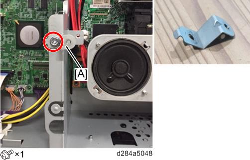
Attach the removed FCU board [A] to the bracket.
Then attach the other end of the flat cable to the connector [B] of CN603 on the removed FCU board.- When inserting the cable, make sure that it is not slanted.
- Make sure that the blue tape of the flat cable faces outward.
- Keep the removed FCU board away from the metal frames. Otherwise, the removed FCU board may have a short circuit.
Turn ON the main power.
SRAM data transmission starts. When the transmission is completed, you will hear a beeper sound.- The beeper sound is at the same volume as the speaker sound.
- The beeper sounds even if the speaker sound is turned off.
- If the beeper does not sound, repeat main power OFF/ON until the beeper sounds, and then perform the transmission procedure. If the data cannot be transmitted, repeat transmission 2 or 3 times.
- When “Ready” is displayed on the display panel, turn OFF the main power. Disconnect the flat cable from the removed FCU board.
- Remove the removed FCU board (
- Remove the bracket from the center frame of the controller box (
- Disconnect the flat cable from the new FCU board.
- Re-assemble the machine.
- Turn ON the main power. Execute SP6-101 to print the system parameter list.
- Check the system parameter list to make sure that the data is transferred correctly.
- Set the correct date and time with the User Tools: User Tools > System Settings > Timer Setting > Set Date/Time.