The ITB unit has a paper transfer belt lift control mechanism for the following reasons (this mechanism moves the ITB into contact with the paper transfer belt or separates them by a small distance, while pressure is applied to the paper transfer belt unit).
- To secure paper transfer efficiency by preventing the ITB bias roller from becoming dented, which may result from the paper transfer belt and the ITB being always in contact.
- To suppress the shock occurred when the paper enters the paper transfer section. (This machine is equipped with the shock jitter cancel mode. The state of paper transfer belt is shifted from the separated state to the contact state when the paper reaches the paper transfer section.)
Control Specifications
- General
The paper transfer belt separation motor [A] drives the cam [B] of the ITB bias roller. The paper transfer belt separation sensor [C] detects the actuator [D]. With this sensor [C], the machine judges whether the paper transfer belt is in contact with the ITB or not. The detected result is fed back to paper transfer belt lift control.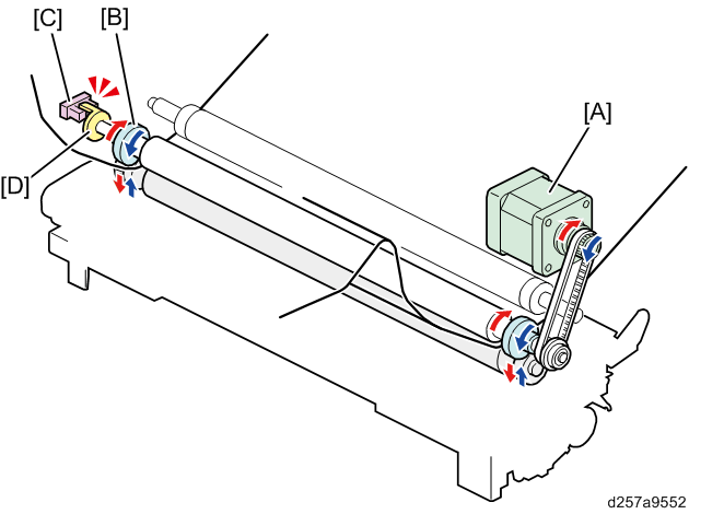
As shown below, The paper transfer belt separation motor [A] rotates clockwise in order to rotate the bias roller cam [B].
[1]: When the paper transfer belt separation motor [A] rotates clockwise, the long diameter part of the bias roller cam [B] contacts with the bearing [D]. The paper transfer belt contacts with the ITB in this state.[2]: When the paper transfer belt separation motor [A] rotates clockwise more, the short diameter part of the bias roller cam [B] contacts with the bearing [D]. The paper transfer belt is separated from the ITB in this state.
You can find whether the paper transfer belt is in contact or separated by seeing the direction of the flat face of the ITB bias roller shaft on which the bias roller cam [B] is attached.
- [1]: Contact state
The flat face of the shaft points to the upper left.
- [2]: Separated state
In the "separated" state, the separation space [C] (indicates the space between the paper transfer belt and the ITB) is 0.8 mm regardless of paper thickness.
- [1]: Contact state
- The direction of the ITB bias roller cam
Separated state
The ITB bias roller cam [B] (bulging part) pushes the bearing of the paper transfer roller [C] down to slightly separate the paper transfer belt from the ITB [A].
Contact state
The ITB bias roller cam [B] (flat part) contacts the bearing [C]. In this state, the paper transfer belt [A] moves up slightly. Sensor State
State of Paper Transfer Belt
Interrupted
Contact
Not interrupted
Separated (Home position)
Contact / Separated State List
The list below shows when "contact / separation" operation is performed:Machine State
Paper Transfer Belt State
Remarks
Ready
Separated
While printing
Color
Contact
The belts are also in contact during intervals between sheets.
BW
Contact
Other States
Process Control
Separated
MUSIC
Separated
Forced Toner Consumption
Separated
Lubrication Mode
Contact
- Shock Jitter Cancel Mode
When the paper enters the nip between the ITB and the paper transfer belt [A] and when the paper exits the nip between the ITB and the paper transfer belt [B], shock will occur.
This can cause jitter on the printout. To cancel this shock jitter, the ITB bias roller is away from the paper transfer belt at the start, then the ITB bias roller contacts the paper transfer belt after the leading edge arrives at the nip, and moves away before the trailing edge passes the nip.
With the default setting, however, shock jitter may occur when thin but hard paper goes between the ITB and the paper transfer belt. To prevent this, it is possible to configure the contact/separation timing for each paper type in SP1-023-001 to 099 (Shock Jitter Cancel). If the paper is custom paper, the contact/separation timing can be set for each paper type using IMSS (Pro C5200S/C5210S only).Shock Jitter Cancel Mode: SP1-023-001 to 099
Change the setting value to "1: ON" ~ "5: LOW 3" for each paper type to adjust the contact/separation timing, so that the shock jitter is improved. (The Default settings are as follows. Thick 1 to 4: "OFF" / Thick 5 to 9 "ON")Setting of SP1-023-001 to 099 Description 0 (OFF) The belts are kept in contact while paper passes the nip area. 1 (ON) The "contact / separation" operation is performed according to the following SP settings: - SP1-021-001 to 099 (Paper Transfer Belt Cont Timing): Contact timing
- SP1-022-001 to 099 (Paper Transfer Belt Set Timing): Separation timing
2 (WEAK)*1 The nip pressure is lowered (decompression mode) according to the following SP settings:
- SP1-025-001 to 099 (Paper Transfer Belt Cont: Depressure): Amount of depressurization
(Pro C5200S/C5210S only)
The machine keep the nip pressure according to the SP settings during printing, not between the sheets.
3 (LOW 1) The machine reduces the separation speed to 85% based on the separation speed of the "1 (ON)" setting. This setting improves the shock jitter at the trailing edge. 4 (LOW 2) The machine reduces the separation speed to 40% based on the separation speed of the "1 (ON)" setting. This setting improves the shock jitter at the trailing edge better than the "3 (LOW 1)" setting. 5 (LOW 3)*1 The machine reduces the separation speed to 40% based on the separation speed of the "1 (ON)" setting, and adjusts the process speed at the same time. This setting is used when the next contact timing is delayed since the separation speed is too low*2. *1 When "2 (WEAK)" or "5 (LOW 3)" is selected, process speed is lowered according to the setting of SP1-023-250.
*2 If the separation is not finished until the next contact timing since the separation speed is too low, the next contact timing is delayed. The machine cannot apply the nip pressure until the target timing, then the transfer at the leading edge of the paper can be less effective.
When "1 (ON)", "3 (LOW 1)", "4 (LOW 2)", or "5 (LOW 3)" is selected, the timing of contact / separation can be adjusted in the SP mode. The thickness and stiffness differ between paper types even if they are in the same paper thickness classification. The adjustment is to compensate for this.
Contact Timing: You can adjust the contact timing when the shock jitter cancel mode (SP1-023-001 to 009) is set to "1 (ON)". Larger SP values mean slower contact timing. Shock jitter at the leading edge could diminish if you delay the contact. However, if the contact timing is delayed too much, transfer at the leading edge of the paper can be less effective.Standard Paper: SP1-021-001 to 099 (Paper Transfer Belt Cont Timing)
Custom Paper (Pro C5200S/C5210S only): No.46 (Ppr Trns Gap: On Timing)
Separation Timing: You can adjust the separation timing when the shock jitter cancel mode (SP1-023-001 to 009) is set to "1 (ON)". Smaller SP values mean an earlier start of the separation. Shock jitter at the trailing edge could diminish if you make the separation earlier. However, if the separation timing is too early, transfer at the trailing edge of the paper can be less effective.
Standard Paper: SP1-022-001 to 099 (Paper Transfer Belt Set Timing)
Custom Paper (Pro C5200S/C5210S only): No.47 (Ppr Trns Gap: Off Timing), 045: (Ppr Trns Contact Mode)
Pressure Reduction Value: You can adjust the nip pressure when the shock jitter cancel mode (SP1-023-001 to 009) is set to "2 (WEAK)". Smaller SP values mean a lower nip pressure. Shock jitter could diminish if you make the nip pressure lowered. However, if the nip pressure is too low, transfer of the whole image can be less effective.Standard Paper: SP1-025-001 to 099 (Paper Transfer Belt Cont: Depressure)
Custom Paper (Pro C5200S/C5210S only): No.49