When you replace the FCU board, transfer the SRAM data from the old FCU board to the new FCU board. Do the following procedure to back up the SRAM data.

- The following data can be transferred: TTI, RTI, CSI, Fax bit switch settings, RAM address settings, NCU parameter settings
- Open the front cover.
Open the rear cover.
Remove the right cover [A].
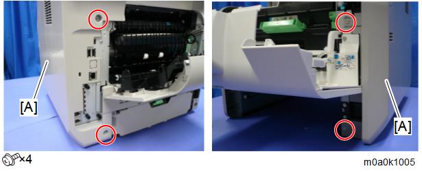
- There are four tabs on the back of the right cover.
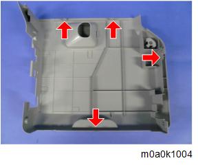
- There are four tabs on the back of the right cover.
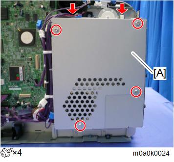
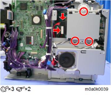
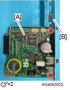
- Remove the controller box cover [A].
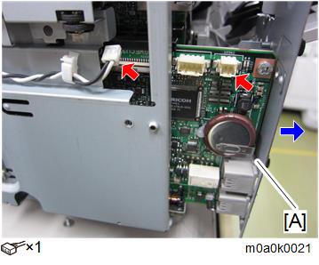
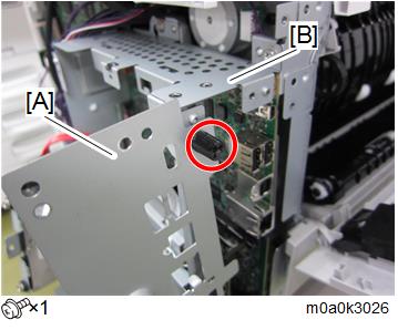
- Remove the screws of the bracket [A] and the FCU board.
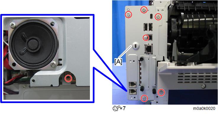
- Disconnect the speaker connector and remove the FCU board [A] with the bracket.
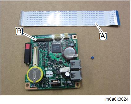
- Change the orientation of the battery jumper switch [A] on the removed FCU board [B], and then attach the battery jumper switch [C]. The battery jumper switch [C] is provided with the new FCU board.
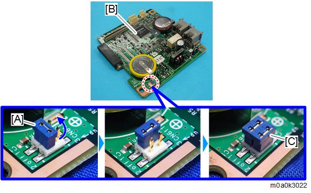
Change the orientation of the battery jumper switch [A] on the new FCU board [B].
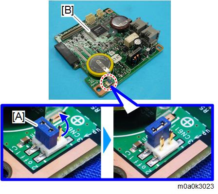
- If the battery jumper switch is not in the correct position, SC820 will occur.
Remove the HDD.
- It is not necessary to disconnect the HDD cable.
Insert one end of the supplied flat cable [A] into the CN603 connector [B] on the new FCU board.
- Make sure that the blue tape of the flat cable faces outward.
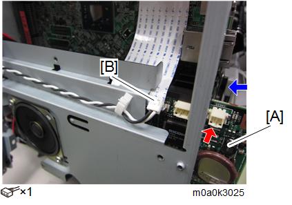
- Insert the new FCU board [A] in the machine and connect the speaker connector [B] to the new FCU board.
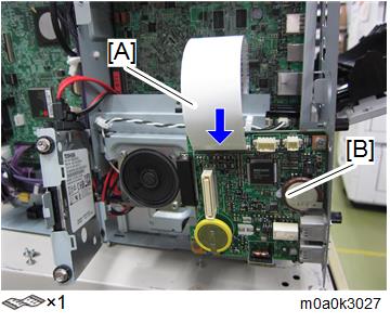
- Mount the old FCU board with bracket [A] to the controller box temporarily.
Insert the other end of the flat cable [A] into the CN603 connector on the old FCU board [B].
- To prevent a short circuit, make sure the old FCU board does not come into contact with anything metal.
- Make sure that the blue tape of the flat cable faces outward.
- Turn the main power switch ON.
The SRAM data transfer begins. Transfer is complete when a beep sounds.
- The volume of the beep is set to the same level as the speaker volume.
- If the speaker volume is set to off, the volume of the beep is set to its initial factory-set level.
- If the machine does not beep, switch the main power off and then back on and try the data transfer again. Try several times if necessary.
- Be sure to check the transfer result after executing data transfer. If the transfer has failed, you need to specify settings manually in the SP mode.
- When "Ready" appears on the control panel, switch the power OFF, and then remove the AC power plug from the receptacle.
- Disconnect the flat cable from both FCU boards.
- Remove the old FCU board with bracket from the controller box.
- Disconnect the speaker connector and remove the new FCU board [A] from the machine.
- Remove the bracket [B] from the old FCU board [A] and attach the bracket to the new FCU board.
- Mount the new FCU board in the machine and connect the speaker connector to the new FCU board.
- Reattach the controller box cover.
- Reattach the cover.
- Turn the main power switch on.
- Enter the SP mode, print the system parameter list from SP6-101 in the Fax SP menu, and then check the list to see whether the SRAM data has been transferred correctly.
Set the correct date and time from the [User Tools].
User Tools > Machine Features > System Settings > Timer Setting > Set Date/Time
- If any of the SRAM data was not transferred, input those settings manually.