When you replace the FCU board, transfer the SRAM data from the old FCU board to the new FCU board. Perform the following procedure to back up the SRAM data.

- The following data can be transferred: TTI, RTI, CSI, Fax bit switch settings, RAM address settings, NCU parameter settings.
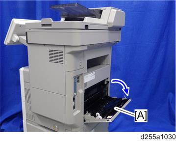
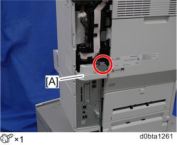
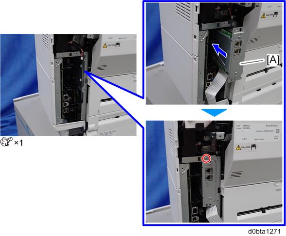
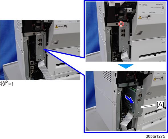
- Open the rear upper cover [A].
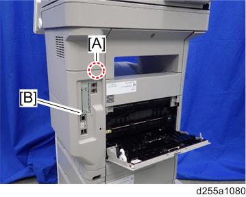
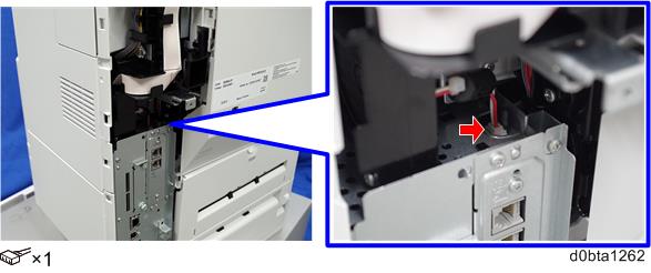
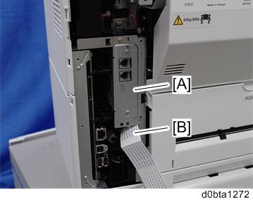
- IM 550F/600F only: Insert a flathead screwdriver into [A] to release a hook of the controller cover [B].
Release the hook by opening the right side of the cover as shown below, and then remove the cover [A] by rotating it in the direction of the blue arrow.
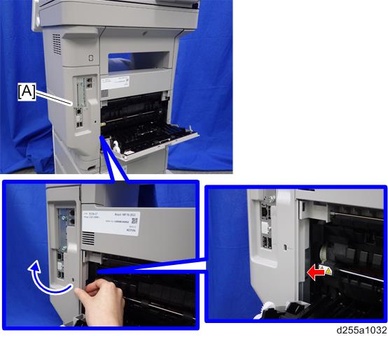
- Be careful not to damage the hooks on the inside of the controller cover when you remove or install the controller cover.
- Be careful not to damage the hooks on the inside of the controller cover when you remove or install the controller cover.
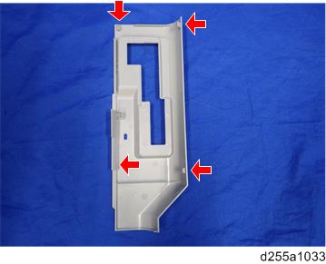
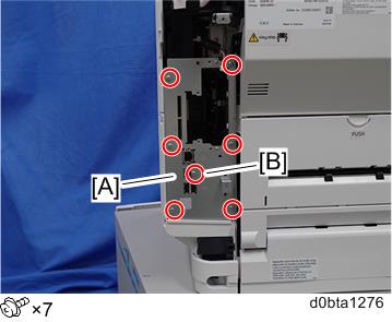
- Insert a flathead screwdriver in the order of
 ,
,  , and
, and  to release three hooks.
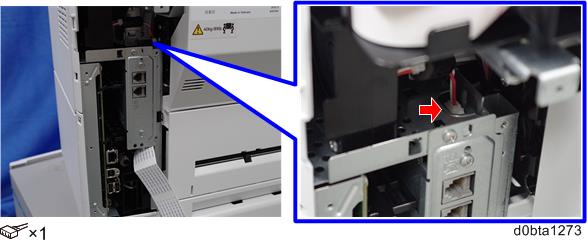
IM 600SRF only: Release the hook .
. Remove the rear left stay [A].
IM 550F/600F: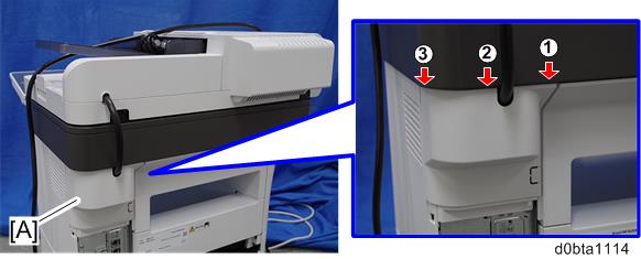
IM 600SRF: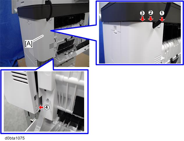
- Be careful not to damage the hooks on the inside of the rear left stay when you remove or install the rear left stay.
IM 550F/600F: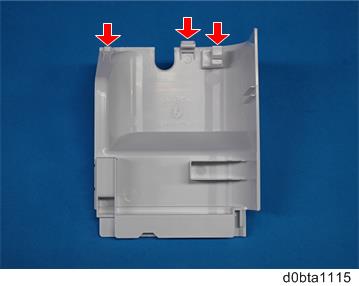
IM 600SRF: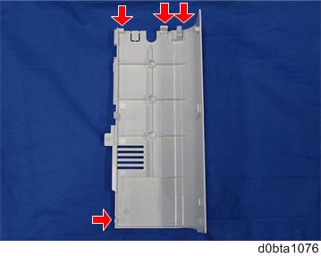
- Be careful not to damage the hooks on the inside of the rear left stay when you remove or install the rear left stay.
- IM 600F only: Remove the cover [A].
- Disconnect the connector of the speaker.
- Remove the fax unit [A].
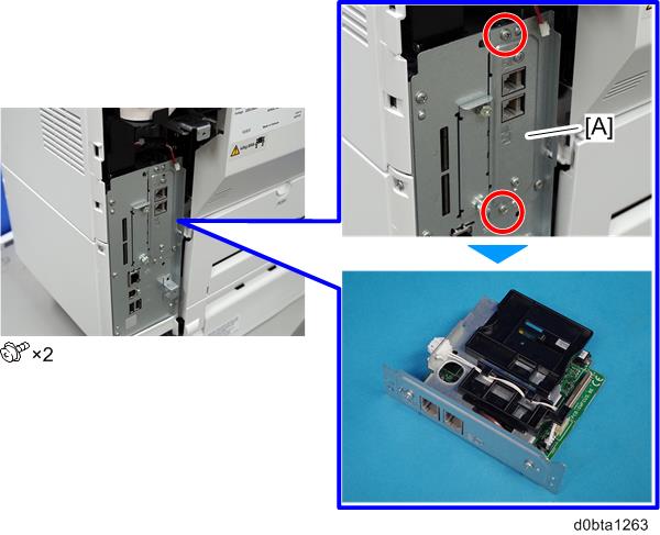
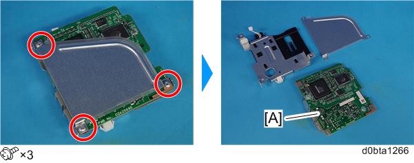
- Remove the bracket [A].
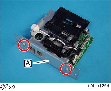
- Disconnect the connector.
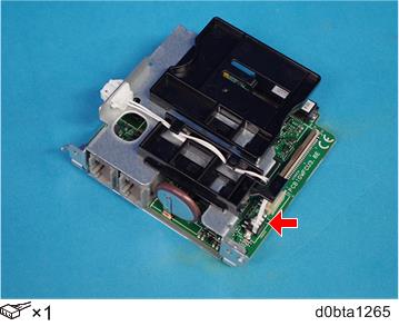
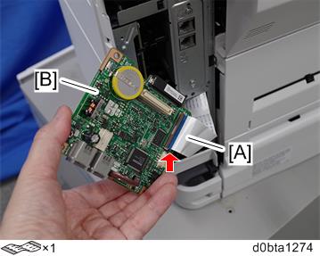
- Remove the FCU board [A].
- Change the orientation of the battery jumper switch [A] on the removed FCU board [B], and then attach the battery jumper switch [C].
The battery jumper switch [C] is provided with the new FCU board.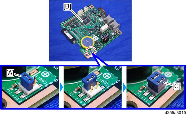
Change the orientation of the battery jumper switch [A] on the new FCU board [B].
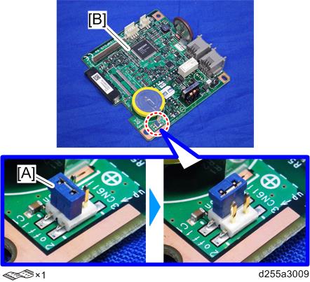
- If the battery jumper switch is not in the correct position, SC820 will occur.
- Install the new FCU board to the fax unit.
- Attach the two brackets [A] to the new FCU board [B].
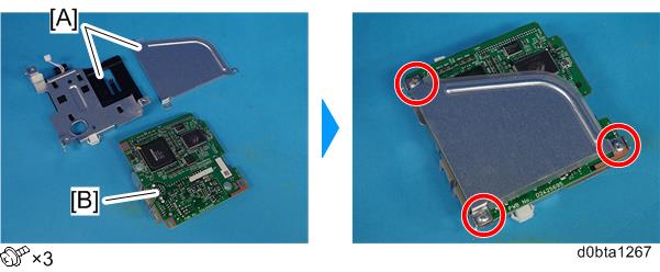
- Connect the connector.
- Attach the bracket [A].
- Attach the two brackets [A] to the new FCU board [B].
- Attach the flat cable [A] to CN603 of the new fax unit.
Make sure that the blue tape of the flat cable faces outward.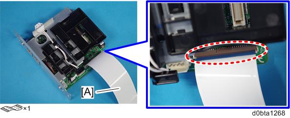
- Remove the slot cover [A].
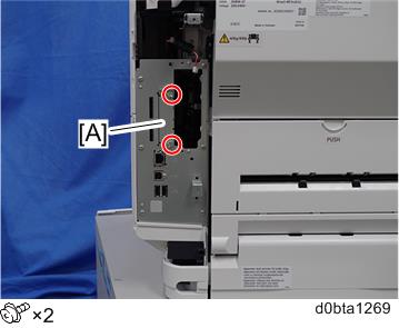
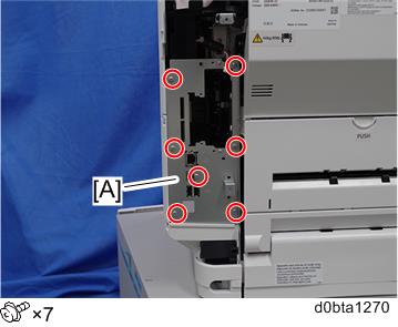
- Remove the controller box cover [A].
Install the new fax unit [A] to the main machine.
- When installing the new fax unit [A], be careful not to damage the flat cable [B]. After installing the new fax unit [A], pull out the flat cable [B] from the main machine, as shown below.
- When installing the new fax unit [A], be careful not to damage the flat cable [B]. After installing the new fax unit [A], pull out the flat cable [B] from the main machine, as shown below.
- Connect the connector of the speaker.
- Connect the flat cable [A] to CN603 of the removed FCU board [B].
Turn ON the main power.
SRAM data transmission starts. When the transmission is completed, you will hear a beeper sound.- The beeper sound is at the same volume as the speaker sound.
- The beeper sounds even if the speaker sound is turned off.
- If the beeper does not sound, repeat the main power OFF/ON until the beeper sounds, and then perform the transmission procedure. If the data cannot be transmitted, repeat transmission 2 or 3 times.
- If the beeper does not sound after turning the main power OFF/ON 3 times, you need to input the settings stored in SRAM memory manually.
- When the message "Ready" is displayed on the operation panel, turn the main power OFF.
- Disconnect the flat cable [A] from the removed FCU board [B].
- Disconnect the connector of the speaker.
- Remove the new FCU board [A] from the main machine.
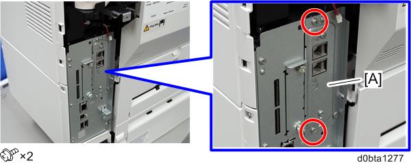
Reattach the controller box cover [A].
- The screw [B] is a small screw. Be careful not to use the wrong screw.
- Reattach the slot cover [A].
- Install the new fax unit [A] to the main machine.
- Connect the connector of the speaker.
- Reassemble the machine.
- Turn ON the main power. Execute SP6-101 to print the system parameter list.
- Check the system parameter list to make sure that the data is transferred correctly.
- Set the correct date and time from the [User Tools].
- User Tools > Machine Features > System Settings > Timer Setting > Set Date/Time
- If any of the SRAM data was not transferred, input those settings manually.