- Operation panel unit (Operation Panel Unit)
- Bottom cover [A] (
 ×4)
×4)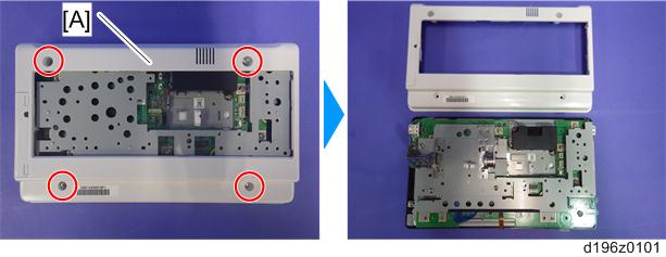

- There are four hooks inside the operation panel unit. Before removing the operation panel bottom cover, check the photos below.
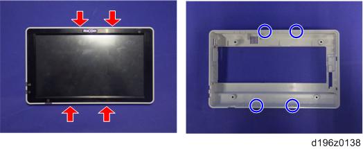
- There are four hooks inside the operation panel unit. Before removing the operation panel bottom cover, check the photos below.
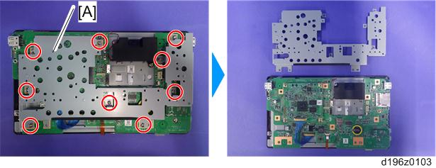
- Base bracket [A] (×9)
- Remove the fixing screws (×4) on the CPU board [A], and remove the CPU board from the micro computer board.
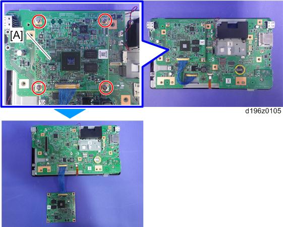
- Make sure that the orientation of the connector is correct when attaching the CPU board.
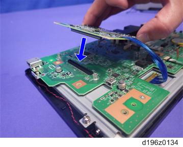
- Make sure that the orientation of the connector is correct when attaching the CPU board.
- Lift the fastener of the LCD I/F cable on the CPU board side.
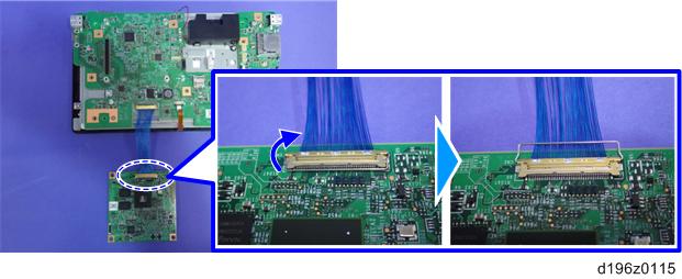
- CPU board [A] (LCD I/F cable ×1)
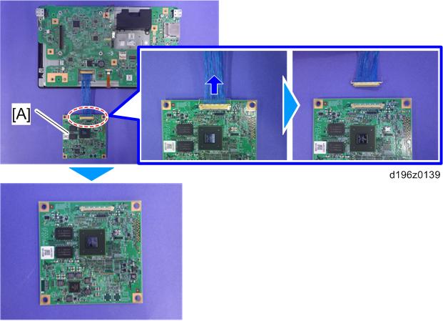
- After replacing the CPU board, make sure that the latest version of the firmware is installed on the Smart Operation Panel. Update it if necessary. (Updating the Smart Operation Panel)