- Turn off the main power switch of the MFP and disconnect the power cord.
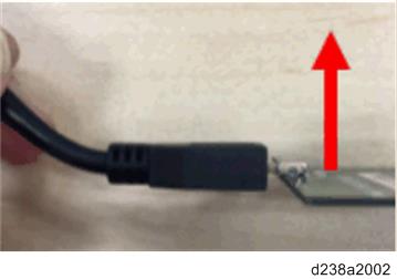
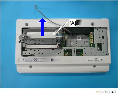
- When handling the operation panel cable, hold down the connector of the cable with your finger as shown in the picture to prevent excessive force from being applied to the connector of the PCB.
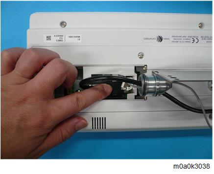
- If excessive force is applied to the connector of the PCB in the direction of the arrow, connection failure may occur.
Remove the operation panel unit from the MFP.

- For details about how to remove the operation panel unit, refer to the service manual for the MFP.
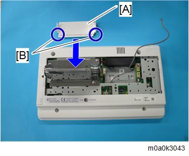
- Remove the rear cover [A] of the operation panel.
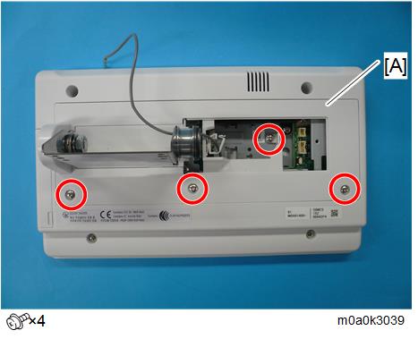
- Slide and remove the arm cover [A].
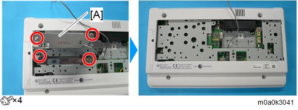
- Remove the operation panel arm bracket [A].
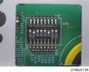
- By factory default, switches No.3 and No.7 of the DIP switch [A] on the micro computer board are set to ON. When installing the operation panel unit, make sure that the DIP switch setting is correct for the MFP on which you are installing the panel.

- The correct DIP switch setting depends on the MFP. Note the DIP switch settings of the old operation panel unit before replacing, and apply the same settings to the new Smart Operation Panel. (Below are two examples for DIP switch settings.)
When No.3 and No.7 are set to ON
- This is the factory default setting of a service part
When only No.3 is set to ON
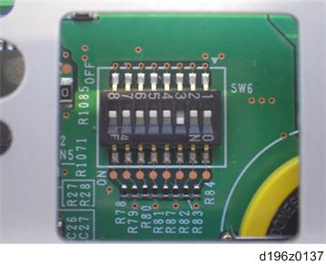
- If the DIP switch setting is wrong, SC672 will be displayed.
- After replacing the operation panel unit, make sure that the latest version of the firmware is installed on the Smart Operation Panel. Update it if necessary (Updating the Smart Operation Panel).
Precaution
When you reinstall the arm cover [A], set the cover so that the cut-offs [B] are placed in the direction shown below.